Surgical retractor for gynecological surgery
A surgical retractor and gynecological surgery technology, applied in the field of medical devices, can solve problems such as uneven force, patient injury, and different forces on the left and right sides of the genitals, achieve accurate pulling position, uniform force, and avoid excessive adjustment speed. quick effect
- Summary
- Abstract
- Description
- Claims
- Application Information
AI Technical Summary
Problems solved by technology
Method used
Image
Examples
Embodiment 1
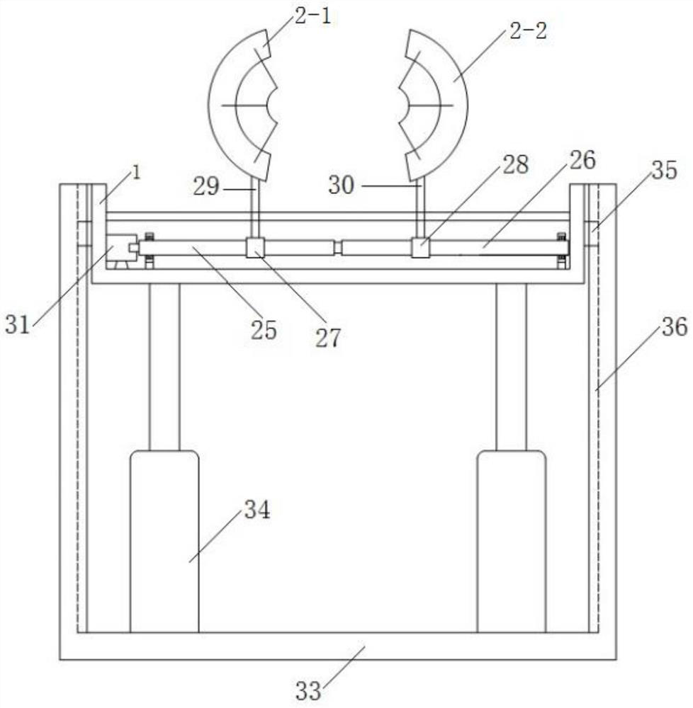
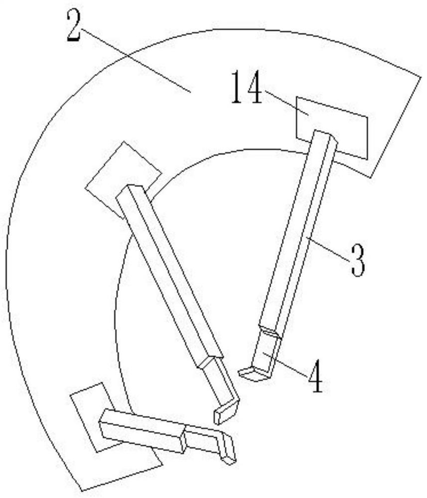
[0061] Such as figure 1 As shown, the embodiment of the present invention provides a surgical retractor for gynecological surgery, including a support base 1, a plate body 2 placed at a certain angle on the support base 1, and a plate body 2 is provided on the plate body 2 for use in the operation. The through hole passing through; the side of the plate body 2 is provided with a plurality of pulling mechanisms that are evenly distributed in the circumferential direction, and each pulling mechanism includes a sleeve rod 3, a slide rod 4 and a hook assembly, and the sleeve rod 3 is connected with the pitch angle adjustment mechanism. The side of the plate body 2 is connected, and the sleeve rod 3 is sleeved with a slide rod 4 slidingly connected to it through the first sliding mechanism. One end of the slide rod 4 sliding out of the sleeve rod 3 is fixed with a hook assembly. The surgical retractor for gynecological surgery also includes a control system, the control system incl...
Embodiment 2
[0068] This embodiment is based on Embodiment 1, the pitch angle adjustment mechanism includes a base 13, the base 13 is fixed on the side of the board body 2, the upper end of the base 13 is hinged with one end of the support plate 14; the sleeve rod 3 is fixed on the upper surface of the support plate 14 ; The base 13 is provided with a screw rod 15, the left and right ends of the screw rod 15 are connected with the bearing seat fixed on the upper surface of the base 13 through bearings, and the screw rod 15 is threaded with the nut 16; the lower surface of the support plate 14 is connected with two supporting The upper end of the rod 17 is hinged, and the lower ends of the two support rods 17 are connected into one body by a connecting rod, and the connecting rod is fixed on the side wall of the nut 16; one end of the screw rod 15 is connected with the output shaft of the second motor 18, and the second motor 18 is fixed On the base 13 , the second motor 18 is also connected...
Embodiment 3
[0071] This embodiment is based on Embodiment 1. The first sliding mechanism includes a first sliding groove 19, which is provided on the left and right sides of the sleeve rod 3; a first sliding bar 20, which is matched with the first sliding groove 19 and fixed on The left and right sides of the slide bar 4; the rack 21 is fixed on the upper side of the slide bar 4; the gear 22 is engaged with the rack 21, and the center of the gear 22 is provided with a second rotating shaft 23 passing through it, The second rotating shaft 23 is located in the second groove provided on the sleeve rod 3, and the left and right sides of the second rotating shaft 23 are connected with the bearing seat fixed in the second groove through bearings; one end of the second rotating shaft 23 is connected to the third The output shaft of the motor 24 is connected, the third motor 24 is fixed in the second groove provided on the sleeve rod 3 , and the third motor 24 is connected with the microprocessor ...
PUM
 Abstract
Description
Claims
Application Information
 - R&D Engineer
- R&D Manager
- IP Professional
- Industry Leading Data Capabilities
- Powerful AI technology
- Patent DNA Extraction
Browse by: Latest US Patents, China's latest patents, Technical Efficacy Thesaurus, Application Domain, Technology Topic, Popular Technical Reports.
© 2024 PatSnap. All rights reserved.Legal|Privacy policy|Modern Slavery Act Transparency Statement|Sitemap|About US| Contact US: help@patsnap.com


