Continuous decontamination device

A technology for decontamination agents and articles, which can be applied to spray devices, water supply devices, liquid spray devices, etc., and can solve problems such as a lot of time and multiple times.

Active Publication Date: 2021-11-12
AIREX
View PDF11 Cites 0 Cited by
  • Summary
  • Abstract
  • Description
  • Claims
  • Application Information

AI Technical Summary

Problems solved by technology

However, in the method using hydrogen peroxide, there is a problem that it takes a lot of time to obtain the desired level of decontamination effect
In addition, there is a problem that more time is required for aeration to remove the hydrogen peroxide film condensed on the surface of the container after decontamination.

Method used


Image

  • Continuous decontamination device
  • Continuous decontamination device
  • Continuous decontamination device

Examples


no. 1 approach >

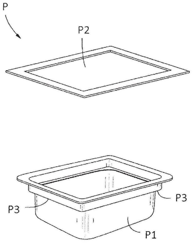
[0055] figure 1 It is a perspective view which shows the storage body (package body) which uses the continuous decontamination apparatus concerning this 1st Embodiment as a decontamination object. However, in the present invention, the shape of the container is not limited to figure 1 shape. exist figure 1 Among them, the package P includes a polyethylene protrusion P1 and a Tyvek (trademark) top surface sealant P2. In the first embodiment, the sterilized syringes used in the filling operation of the plurality of prefilled syringes are housed therein and decontaminated in a sealed state.

[0056] Next, the continuous decontamination device according to the first embodiment will be described. image 3 It is a schematic plan view showing the continuous decontamination device according to the first embodiment, Figure 4 It is a schematic front view showing the continuous decontamination device. The continuous decontamination device according to the first embodiment includes...

no. 2 approach >

[0093] In this second embodiment, the number and arrangement of vibrating disks of the mist control device are changed with respect to the above-mentioned first embodiment. Figure 11 It is a schematic diagram showing the relationship between the mist supply device and the mist control device according to the second embodiment. Figure 11 (A) is a front cross-sectional view of the package P placed on the roller conveyor 114 as viewed toward the traveling direction. Figure 11 (B) is a side cross-sectional view of the package P placed on the roller conveyor 114 as viewed from the transverse direction of the traveling direction (arrow direction in the figure).

[0094] exist Figure 11 In the inside of the decontamination area 112 of the apparatus main body 110a, the package P is placed and conveyed on the roller conveyor 114. In this second embodiment, the same two-fluid nozzle 130 as in the above-mentioned first embodiment is used as the mist supply device 130 , and is insta...


PUM


Abstract

Provided is a continuous decontamination device which uses a decontamination agent such as hydrogen peroxide, which has been widely used in recent years, without using a high-priced electron accelerator, and is capable of achieving of treatment in a short amount of time while achieving a uniform decontamination level at each section and thereby is capable of batch treatment of articles to be decontaminated. The continuous decontamination device is provided with a device body that has a decontamination region and an aeration region, a conveyance means that conveys an article, a mist supply means, a mist control means, and an aeration means. The mist supply means converts the decontamination agent into a decontamination agent mist and supplies the same into the decontamination region. The mist control means is provided with a vibration board disposed in the vicinity of an inner wall of the decontamination region and causes the vibration board to ultrasonically vibrate to generate an acoustic flow formed by ultrasonic waves in a perpendicular direction from the board face. By causing a pressing force from the acoustic radiation pressure to act on the decontamination agent mist supplied into the decontamination region, the decontamination agent mist is concentrated on the outer surface of the article that is conveyed inside the decontamination region by the conveyance means.

Description

technical field [0001] The present invention relates to a continuous decontamination device for continuously decontaminating the outer surface of an article by decontamination agent mist, and transporting the decontaminated article to a working room in a sterile environment. Background technique [0002] From the viewpoint of convenience at the medical site, prefilled syringes, prefilled vials, and the like filled with pharmaceuticals are manufactured in advance. The work of filling these syringes, vials, etc. with pharmaceuticals is performed in a filling work room (hereinafter referred to as "sterile work room") under an aseptic environment. The syringes, vials, etc. used in this work are small parts one by one, and the number of handling needs to be large. Therefore, these syringes, vials, etc. are sterilized by gamma ray irradiation, electron beam irradiation, EOG (ethylene oxide gas) etc. at each manufacturing stage, and are carried in in a state where a predetermined ...

Claims


Application Information

Patent Timeline
Patent Type & Authority Applications(China)
IPC IPC(8): A61L2/025A61L2/18
CPCA61L2/22A61L2202/16A61L2202/23A61L2202/24A61L2202/14B05B13/0221B05B17/0607B05B7/0075B05B7/2489A61L2/0088A61L2/025B06B1/0607A61L2/18A61L2/26B05B17/06A61L2202/11A61L2202/15A61L2202/122G10K11/34
Inventor 川崎康司角田大辅益留纯二村春华矢崎至洋北野司郭志强小川亚由美
Owner AIREX
Why Eureka
Try Eureka