
Multi-station pickup device for electronic part machining

A technology for electronic parts and pick-up devices, applied in the field of electronics, can solve the problems of operator's hand scratches, waste of human resources, increased production costs, etc., and achieve the effects of ensuring personnel safety, improving clamping accuracy, and preventing damage.

Inactive Publication Date: 2021-11-12
嘉兴市女兆东科技有限公司
View PDF0 Cites 0 Cited by
  • Summary
  • Abstract
  • Description
  • Claims
  • Application Information

AI Technical Summary

Problems solved by technology

[0002] Due to the gradual improvement of automation equipment, people's living standards are increasing day by day. Automation equipment has effectively replaced traditional operations. requirements, while ensuring the safety and stability of electronic components in the production process, using mechanical automation picking equipment, and if traditional manual operations are adopted, not only will more human resources be wasted and production costs will increase, but at the same time, in In the process of manual operation, for these specific electronic parts, the staff needs to maintain a high degree of concentration during the operation to prevent the parts from being damaged during the picking process. At the same time, for some rough electronic parts, during the picking process, it may It will cause scratches on the hands of the operator, and workers wearing protective gloves cannot achieve the precision in the production of electronic parts. Therefore, a picking device suitable for multi-station picking up electronic parts is designed here

Method used


Image

  • Multi-station pickup device for electronic part machining
  • Multi-station pickup device for electronic part machining
  • Multi-station pickup device for electronic part machining

Examples


Embodiment Construction

[0021] The following will clearly and completely describe the technical solutions in the embodiments of the present invention with reference to the accompanying drawings in the embodiments of the present invention. Obviously, the described embodiments are only some, not all, embodiments of the present invention. Based on the embodiments of the present invention, all other embodiments obtained by persons of ordinary skill in the art without making creative efforts belong to the protection scope of the present invention.

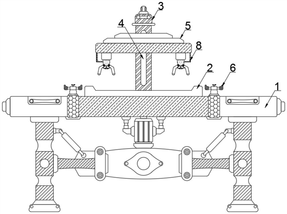
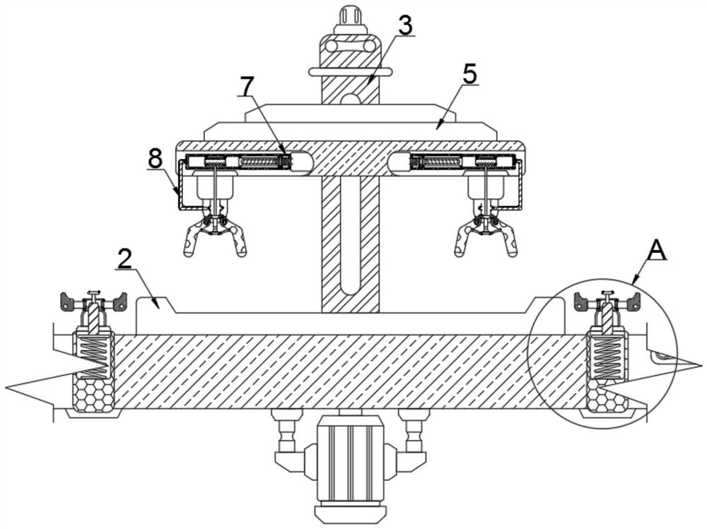
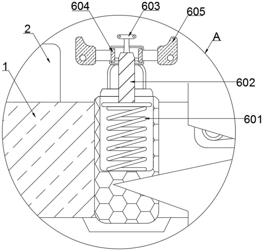
[0022] see Figure 1-Figure 7, a pick-up device for multi-station electronic parts processing, comprising an operating table 1, a stabilizing assembly 6, a moving assembly 7 and a gripping assembly 8, the top outer wall of the vertical center line of the operating table 1 is fixedly equipped with a storage tray 2, the operating table The inner wall of the vertical center line of 1 is rotatably connected with a moving column 3, and the inner wall of the vertica...


PUM


Abstract

The invention relates to the technical field of electronics, and discloses a multi-station pickup device for electronic part machining. The device comprises an operation table, a stabilizing assembly, a moving assembly and a clamping assembly, an object placing disc is fixedly installed on the outer wall of the top end of the vertical center line of the operation table, and a moving column is rotationally connected to the inner wall of the vertical center line of the operation table; in the process that an air pump inflates a telescopic frame, a sliding disc can be pushed to move in the direction close to a rotating roller, so that a threaded rod is driven to be in contact with the rotating roller, threads on the threaded rod are matched with a threaded block on the rotating roller to drive the rotating roller to rotate, a pull rope is pulled, and the pull rope assists in pulling a bidirectional telescopic block; the two-way telescopic block moves upwards to enter a groove in the upper portion, so that two clamping arms are driven to swing towards the opposite sides, electronic parts are clamped, manual operation is replaced, the personnel safety is guaranteed, meanwhile, the clamping precision and the placing station precision are improved, and the situation that the electronic parts are damaged is also prevented.

Description

technical field [0001] The invention relates to the field of electronic technology, in particular to a pick-up device for processing multi-station electronic parts. Background technique [0002] Due to the gradual improvement of automation equipment, people's living standards are increasing day by day. Automation equipment has effectively replaced traditional operations. requirements, while ensuring the safety and stability of electronic components in the production process, using mechanical automation picking equipment, and if traditional manual operations are adopted, not only will more human resources be wasted and production costs will increase, but at the same time, in In the process of manual operation, for these specific electronic parts, the staff needs to maintain a high degree of concentration during the operation to prevent the parts from being damaged during the picking process. At the same time, for some rough electronic parts, during the picking process, it may...

Claims


Application Information

Patent Timeline
IPC IPC(8): B65G47/90
CPCB65G47/90B65G47/901B65G2207/40B65G2201/02
Inventor 陆春伟
Owner 嘉兴市女兆东科技有限公司
Learn More