
Efficient shading glass curtain new material

A glass curtain wall and new material technology, applied in metal processing and other directions, can solve problems such as pollution and affecting use

Inactive Publication Date: 2021-11-12
南京宣汉玻璃有限公司
View PDF0 Cites 0 Cited by
  • Summary
  • Abstract
  • Description
  • Claims
  • Application Information

AI Technical Summary

Problems solved by technology

[0002] The side wall of the glass curtain wall will be polluted by light, and coated glass or coated glass will be used on the curtain wall of high-rise buildings. When the light directly hits the side wall of the glass, it will be reflected by the flat optical fiber of the glass. During the installation process, the glass for making the curtain wall will be cut according to the actual size required on site. The side wall of the glass is too large. Hard, at this time the edge of the knife used to cut it is also sharp and fast, and there will be too much friction between the cross-section of the glass, causing the fine particles between the cuts to be quickly driven to the outside, these The fine glass fragments will jump to the side wall of the glass curtain wall with the centrifugal force, causing pit marks, which will affect the later use

Method used


Image

  • Efficient shading glass curtain new material
  • Efficient shading glass curtain new material
  • Efficient shading glass curtain new material

Examples


Embodiment 1

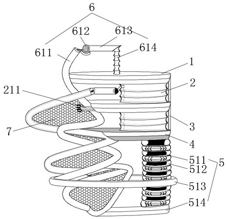
[0034] see figure 1 and Figure 4 , a cutting device for an efficient light-shielding glass curtain wall, comprising a movable plate 1, a half-circle plate 101 is arranged on the side of the movable plate 1, an elastic ring 102 is connected through the inside of the movable plate 1, and the bottom side wall of the movable plate 1 A rotating mechanism 2 is connected through it, and the inside of the rotating mechanism 2 includes a connecting pipe 211, the inner end of the connecting pipe 211 is connected with a sliding ring 215, the side wall of the sliding ring 215 is connected with a bracket 214, and the side wall of the sliding ring 215 is A support pipe 212 is connected through it, and a ball 213 is connected through the end of the support pipe 212 far away from the bracket 214. A support rod 3 is connected through the side of the movable plate 1, and a base plate 4 is connected through the bottom end of the support rod 3. The base plate The bottom of 4 is connected with s...

Embodiment 2

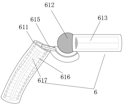
[0039] see Figure 1-2 , a cutting device for an efficient light-shielding glass curtain wall, comprising a movable plate 1, a half-circle plate 101 is arranged on the side of the movable plate 1, an elastic ring 102 is connected through the inside of the movable plate 1, and the bottom side wall of the movable plate 1 A rotation mechanism 2 is connected through it, a support rod 3 is connected through the side of the movable plate 1, a base plate 4 is connected through the bottom end of the support rod 3, and a spring pressing mechanism 5 is connected through the bottom of the base plate 4. The twitching mechanism 6 is connected through the top side wall, and the inside of the twitching mechanism 6 includes an elastic tube 611. The inner axis of the elastic tube 611 is connected with a central column 617, and the side wall of the central column 617 is connected with a needle bar 616. The top of the central column 617 is connected with a connecting column 615, the right end of...

Embodiment 3

[0044] see figure 1 and image 3 , a cutting device for an efficient light-shielding glass curtain wall, comprising a movable plate 1, a half-circle plate 101 is arranged on the side of the movable plate 1, an elastic ring 102 is connected through the inside of the movable plate 1, and the bottom side wall of the movable plate 1 A rotating mechanism 2 is connected through it, a support rod 3 is connected through the side of the movable plate 1, a base plate 4 is connected through the bottom end of the support rod 3, and a spring pressing mechanism 5 is connected through the bottom of the base plate 4. The interior includes a support block 511, the side wall of the support block 511 is connected with an air bag 512, the outer wall of the support block 511 is connected with a movable ring 513, the bottom end of the support block 511 is connected with a connecting rod 514, and the movable plate 1 The twitching mechanism 6 is connected through the top side wall, and the inside of...


PUM


Abstract

The invention relates to the technical field of glass curtain walls, and discloses an efficient shading glass curtain wall cutting device. The s to the technical field of glass curtain walls, and discloses an efficient shading glass curtain wall cutting device comprises a movable plate; a semi-circle plate is arranged on the side of the movable plate; an elastic ring is connected to the interior of the movable plate in a penetrating mode; a rotating mechanism is connected to the bottom side wall of the movable plate in a penetrating mode; and the bottom of the base plate is connected with an elastic pressing mechanism in a penetrating mode. A connecting column is tilted upward to hold the bottom side of a movable bead, the side wall of the movable bead impacts the side wall of a channel pipe, gas on the outer side is pushed into the channel pipe, gas in the channel pipe is poured into a sectional pipe, the side wall of the sectional pipe bulge towards the periphery, cracks in the side wall of the sectional pipe are exploded, and gas in the sectional pipe is extruded outwards and blown to the outer peripheral wall of the movable plate; and at the moment, when the side wall of the movable plate slides downwards, surrounding dust can be prevented from approaching and being sucked into an internal gap of the device to cause machine blockage.

Description

technical field [0001] The invention relates to the technical field of glass curtain walls, in particular to a new high-efficiency light-shielding glass curtain wall material. Background technique [0002] The side wall of the glass curtain wall will be polluted by light, and coated glass or coated glass will be used on the curtain wall of high-rise buildings. When the light directly hits the side wall of the glass, it will be reflected by the flat optical fiber of the glass. During the installation process, the glass for making the curtain wall will be cut according to the actual size required on site. The side wall of the glass is too large. Hard, at this time the edge of the knife used to cut it is also sharp and fast, and there will be too much friction between the cross-section of the glass, causing the fine particles between the cuts to be quickly driven to the outside, these The fine glass shatters will jump to the side wall of the glass curtain wall with the centrif...

Claims


Application Information

Patent Timeline
Patent Type & Authority Applications(China)
IPC IPC(8): B26D7/27B26D7/18B29C67/24B29C37/00C08L83/04C08L79/08C08K3/04
CPCB26D7/27B26D7/1863B29C67/24B29C37/00C08L83/04B29C2037/90C08L79/08C08K3/04
Inventor 杜峥嵘
Owner 南京宣汉玻璃有限公司
Learn More