
Machining method for power supply accessories of new energy automobile and machining device

A technology for new energy vehicles and processing devices, which is applied in metal processing equipment, maintenance and safety accessories, metal processing machinery parts, etc. The effect of deviation

Active Publication Date: 2021-11-12
徐州大工电子科技有限公司
View PDF5 Cites 0 Cited by
  • Summary
  • Abstract
  • Description
  • Claims
  • Application Information

AI Technical Summary

Problems solved by technology

[0002] The new energy vehicle power supply box is a new energy vehicle power supply accessory. In the production and processing, a drilling machine is required to process the holes, and a cutting fluid is used to advance the cooling process during the processing, while the existing machine tool uses a liquid storage box The cutting fluid is stored and placed, but during the continuous operation of the machine tool, the user does not know the usage of the cutting fluid in the storage box, so when the cutting fluid is used up and the machine tool is still working, it will affect the processing of accessories

Method used


Image

  • Machining method for power supply accessories of new energy automobile and machining device
  • Machining method for power supply accessories of new energy automobile and machining device
  • Machining method for power supply accessories of new energy automobile and machining device

Examples


Embodiment 1

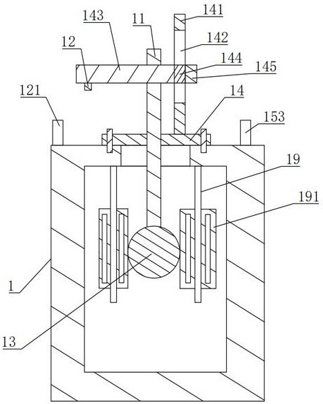
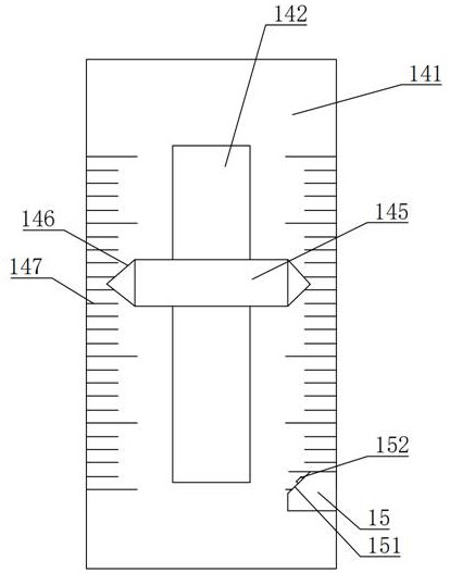
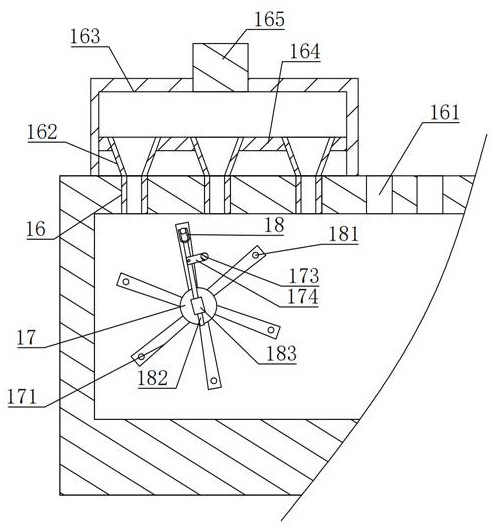
[0025] Embodiment 1: A kind of new energy vehicle power supply accessories processing device, such as figure 1 and figure 2 , including a liquid storage box 1 set on the machine tool and used to store cutting fluid. A detection rod 11 is vertically slidably connected to the wall of the upper end of the liquid storage box 1. One end of the detection rod 11 enters the liquid storage box 1, and the other end Located at the upper end of the liquid storage box 1, and the detection rod 11 is provided with a distance sensor 12 for measuring the distance from the distance sensor 12 to the upper end wall of the liquid storage box 1 at one end extending out of the outer wall of the upper end of the liquid storage box 1, and the outer wall of the upper end of the liquid storage box 1 is provided with There is an alarm light 121 controlled by the distance sensor 12, a floating ball 13 is provided on the side of the detection rod 11 located in the liquid storage box 1, and a limit piece i...

Embodiment 2

[0035] Embodiment 2: A processing method according to the above embodiment 1, including fixing the plate to be processed of the new energy vehicle power box body on the drilling machine through the fixture, and then starting the drilling machine, the cutting fluid is extracted from the liquid storage box 1 and It is poured on the position where the plate to be processed is processed. With the work of the drilling machine, the liquid level of the chip liquid in the liquid storage box 1 gradually decreases, and the floating ball 13 also decreases. When the distance collected by the distance sensor 12 is less than the preset value, the control The warning light 121 lights up.


PUM


Abstract

The invention discloses a machining method for power supply accessories of a new energy automobile and a machining device, and relates to the technical field of power supply accessory machining. The machining method for the power supply accessories of the new energy automobile and the machining device have the advantages that cutting liquid in a liquid storage box is monitored, a user is conveniently reminded to fill the liquid storage box with the cutting liquid, according to the technical solution, a detection rod is vertically and slidably connected to the box wall of the upper end of the liquid storage box, one end of the detection rod enters the liquid storage box, the other end of the detection rod is located at the upper end of the liquid storage box, the end, extending out of the outer wall of the upper end of the liquid storage box, of the detection rod is provided with a distance sensor used for measuring the distance between the distance sensor and the box wall of the upper end of the liquid storage box, an alarm lamp controlled by the distance sensor is arranged on the outer wall of the upper end of the liquid storage box, a floating ball is arranged on the side, located in the liquid storage box, of the detection rod, and a limiting piece enabling the detection rod to vertically move is arranged on the liquid storage box.

Description

technical field [0001] The invention relates to the technical field of power supply accessories processing, in particular to a processing method and a processing device for new energy vehicle power supply accessories. Background technique [0002] The new energy vehicle power supply box is a new energy vehicle power supply accessory. In the production and processing, a drilling machine is required to process the holes, and a cutting fluid is used to advance the cooling process during the processing, while the existing machine tool uses a liquid storage box The cutting fluid is stored and placed, but during the continuous operation of the machine tool, the user does not know the usage of the cutting fluid in the storage box, so when the cutting fluid is used up and the machine tool is still working, it will affect the processing of accessories . Contents of the invention [0003] In view of the above-mentioned technical deficiencies, the purpose of the present invention is...

Claims


Application Information

Patent Timeline
IPC IPC(8): B23Q11/00B23Q11/10
CPCB23Q11/0089B23Q11/10
Inventor 刘运胜孟陆
Owner 徐州大工电子科技有限公司
Learn More