Sewage recovery and reuse apparatus

A sewage recovery and filtration device technology, applied in water/sewage treatment, water/sewage multi-stage treatment, water/sludge/sewage treatment, etc., can solve problems such as poor adaptability, high use limitations, and inability to adjust. Achieve the effect of reducing the limitation of use, improving the adaptability and improving the reliability

Inactive Publication Date: 2017-09-22
JIANGSU GUANGSHENGYUAN TECH DEV
View PDF0 Cites 5 Cited by
  • Summary
  • Abstract
  • Description
  • Claims
  • Application Information

AI Technical Summary

Problems solved by technology

[0002] As we all know, a sewage recovery and reuse device is an auxiliary device used in the sewage treatment process to filter it so that it can be recycled and reused. It has been widely used in the field of sewage treatment; the existing sewage recovery and reuse The utilization device includes a working box, four sets of brackets and multiple sets of filtering devices. There is a working chamber inside the working box, and multiple sets of filtering devices are installed inside the working chamber. The tops of the four sets of brackets are respectively installed on the left and right front sides of the bottom of the working box , left rear side and right rear side, the top left side of the work box is connected with a water inlet pipe, and a water inlet valve is arranged on the water inlet pipe, and the bottom end of the right side of the work box is connected with a water outlet pipe, and a water outlet pipe is provided Water outlet valve; when the existing sewage recycling device is used, the sewage is introduced into the working chamber through the water inlet pipe, and it is filtered multiple times through multiple sets of filter devices, and finally the filtered sewage is discharged and collected through the water outlet pipe. Yes; in the use of the existing sewage recovery and reuse device, it is found that the height of the working box is fixed and cannot be adjusted according to the actual situation, resulting in poor adaptability and high use limitations; and the function of the working box is relatively single, resulting in its Poor practicability; and when the temperature of the sewage is too high, it cannot help it cool down, resulting in poor reliability

Method used


Image

  • Sewage recovery and reuse apparatus
  • Sewage recovery and reuse apparatus
  • Sewage recovery and reuse apparatus

Examples


Embodiment Construction

[0014] The specific implementation manners of the present invention will be further described in detail below in conjunction with the accompanying drawings and embodiments. The following examples are used to illustrate the present invention, but are not intended to limit the scope of the present invention.

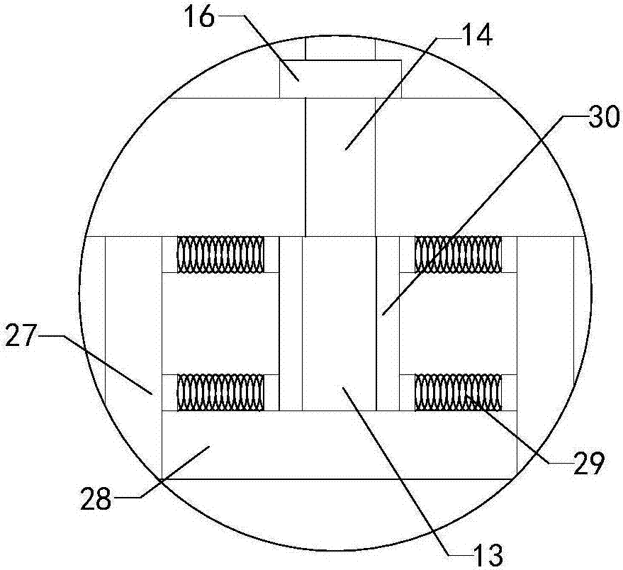
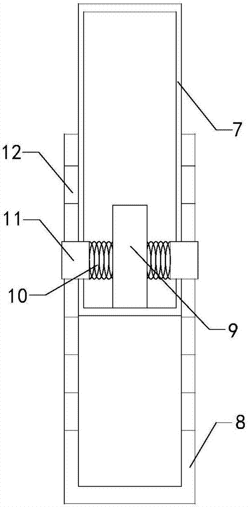
[0015] Such as Figure 1 to Figure 3 As shown, a kind of sewage recycling device of the present invention comprises working box 1, four sets of brackets and multiple groups of filtering devices 2, and a working chamber is arranged in the working box, and multiple groups of filtering devices are installed inside the working chamber, and the working box A water inlet pipe 3 is connected to the left top, and a water inlet valve 4 is arranged on the water inlet pipe; an outlet pipe 5 is connected to the right bottom of the work box, and an outlet valve 6 is arranged on the outlet pipe; It includes inserting posts 7, intubation tubes 8, limit posts 9, two sets of limit springs...


PUM


Abstract

The invention relates to the technical field of a sewage treatment attachment device and particularly relates to a sewage recovery and reuse apparatus. The height of a working box can be adjusted according to the actual situation so that adaptability is improved and use limitation is reduced. The working box has multiple functions and practicality is improved. When the sewage temperature is too high, the device can cool the sewage and improves reliability. The sewage recovery and reuse apparatus comprises the working box, four supports and multiple filters. A working chamber is arranged in the working box. Each one of the four supports comprises insert columns, insert pipes, limited posts, two limiting springs and two limiting blocks. The left and right side walls of the insert column are respectively provided with a left through hole and a right through hole. The left and right side walls of the insert pipe are respectively provided with multiple left limiting holes and multiple right limiting holes along a longitudinal direction. A motor is arranged below the working box. An output end at the top of the motor is provided with a transmission shaft. The transmission shaft is provided with stirring blades. The outer side wall of the transmission shaft is provided with a seal ring. The sewage recovery and reuse apparatus comprises a jacket. A cooling chamber is arranged in the jacket.

Description

technical field [0001] The invention relates to the technical field of sewage treatment attachments, in particular to a sewage recovery and reuse device. Background technique [0002] As we all know, a sewage recovery and reuse device is an auxiliary device used in the sewage treatment process to filter it so that it can be recycled and reused. It has been widely used in the field of sewage treatment; the existing sewage recovery and reuse The utilization device includes a working box, four sets of brackets and multiple sets of filtering devices. There is a working chamber inside the working box, and multiple sets of filtering devices are installed inside the working chamber. The tops of the four sets of brackets are respectively installed on the left and right front sides of the bottom of the working box , left rear side and right rear side, the top left side of the work box is connected with a water inlet pipe, and a water inlet valve is arranged on the water inlet pipe, a...

Claims


Application Information

Patent Timeline
Patent Type & Authority Applications(China)
IPC IPC(8): B01D36/00B01D29/03B01D29/56B01D35/00B01D35/16B01D35/18C02F9/02
CPCB01D29/03B01D29/56B01D35/00B01D35/16B01D35/18B01D36/00C02F1/00C02F1/001
Inventor 金传广尤汉春宋大顺李欣欣陈西府徐晓洪刘兆诚
Owner JIANGSU GUANGSHENGYUAN TECH DEV
Why Eureka
Try Eureka