Heating device for winter construction of construction project and using method
A technology for construction projects and installation tanks, which is applied in the field of building indoor insulation, can solve the problems of affecting the thermal energy conversion rate of heating devices and the inability to fully burn solid fuels, and achieve the effect of increasing the thermal energy conversion rate and improving the thermal energy conversion rate
- Summary
- Abstract
- Description
- Claims
- Application Information
AI Technical Summary
Problems solved by technology
Method used
Image


Examples
Embodiment 1
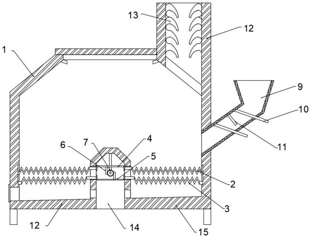
[0029] Embodiment 1: as Figure 1 to Figure 2 As shown, a construction heating device for winter construction includes a furnace body 1, a grate one 2 and a grate two 3 installed inside the furnace body 1, the two are arranged up and down and are slidably matched with the inner wall of the furnace body 1, and installed Inside the body of furnace 1 and used to adjust the adjustment mechanism for the up-and-down movement of the first 2 and the second 3 of the fire grate, the mesh size of the second 3 of the fire grate is smaller than the mesh size of the first 2 fire grate. Utilize grate one 2 and grate two 3 on the upper and lower sides, because the meshes of the two are different, the solid fuel on the grate one 2 on the upper side will stretch outwards after being burned to form a fragile solid After the particles are adjusted up and down, the fragmented solid fuel will fall to the grate 2 3 with denser meshes in the lower layer to continue to exert waste heat and improve the...
Embodiment 2
[0032] Embodiment 2: further preferred scheme on the basis of embodiment 1:
[0033] The grate one 2 and the grate two 3 are tooth-shaped plate structures, and the tooth shapes of the two are staggered. The mesh of the grate one 2 is matched with the mesh of the grate two 3. The mesh of flute matches with the mesh of fire grate-2. When the adjustment lever 8 is driven to drive the gear 7 to move the rack up and down, the grate one 2 and the two grate 3 will also move relative or opposite to each other. The mesh of the grate will be adapted to screen the solid fuel. At the same time, the solid fuel on the grate 2 will fall to the grate 2 after being broken. When it contacts the grate 2, it will be broken again and fall to the ash plate 15 on.
Embodiment 3
[0034] Embodiment 3: On the basis of Embodiment 2, in order to prevent the solid fuel being burned from being covered by excessive addition during the feeding process and cannot be fully burned, or the addition of too little leads to the need for multiple additions, a further preferred solution:
[0035] The side of the body of furnace 1 is provided with a charging cylinder 9, and the inside of the charging cylinder 9 is equipped with a fixed baffle 11 and movable baffles 10 installed on both sides of the fixed baffle 11, and the feeding cylinder 9 is controlled by opening and closing the two movable baffles 10. A single addition of internal solid fuel.
[0036] When solid fuel needs to be added inside the body of furnace 1, first open the movable baffle 10 on the upper side of the charging cylinder 9 to quantitatively move the solid fuel into the fixed baffle 11, then close the movable baffle 10 on the upper side, and open the lower side The movable baffle 10 of the solid fue...
PUM
 Abstract
Description
Claims
Application Information
 - Generate Ideas
- Intellectual Property
- Life Sciences
- Materials
- Tech Scout
- Unparalleled Data Quality
- Higher Quality Content
- 60% Fewer Hallucinations
Browse by: Latest US Patents, China's latest patents, Technical Efficacy Thesaurus, Application Domain, Technology Topic, Popular Technical Reports.
© 2025 PatSnap. All rights reserved.Legal|Privacy policy|Modern Slavery Act Transparency Statement|Sitemap|About US| Contact US: help@patsnap.com