Liftable flood control embankment and method

A technology of embankments and levees, applied in the field of liftable flood control embankments, which can solve the problems of complex structure, high cost, and high production cost

Active Publication Date: 2022-05-20
山东乾元工程集团有限公司东营维修养护分公司
View PDF9 Cites 0 Cited by
  • Summary
  • Abstract
  • Description
  • Claims
  • Application Information

AI Technical Summary

Problems solved by technology

The existing problems are: high production cost and complex structure, resulting in high cost, and cannot be fully extended to river embankments, and can only be applied to the reconstruction of local river embankments, such as the transformation and protection of key areas
The existing problem is: due to the very long length of the river embankment, the automatic flood wall used in this patent needs to be controlled by the controller to lift up and down, which will cause a problem, one is the construction cost of the long-distance installed automatic flood wall It is very high, and the self-weight of the automatic flood control wall is very large. The long-distance flood control wall requires a lot of hydraulic mechanisms to drive the lifting height. Second, the lifting of the automatic flood control wall requires the guarantee of electricity. However, in the rainy season, it is difficult to obtain electricity. , this will appear when the automatic flood wall needs to be raised, without power, it will not be able to realize the raising function it should provide

Method used


Image

  • Liftable flood control embankment and method
  • Liftable flood control embankment and method
  • Liftable flood control embankment and method

Examples


Embodiment 1

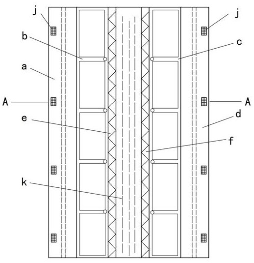
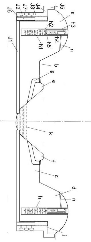
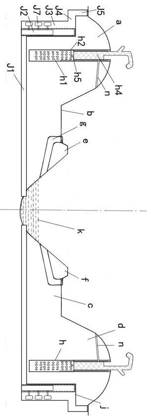
[0046] Embodiment 1, with reference to Figure 1-3 , a kind of liftable flood control embankment mentioned in the present invention, comprises the river protection embankment a on the left bank, the river beach b on the left bank, the river beach c on the right bank, the river protection embankment d on the right bank, the left water and soil loss prevention dam e, the right water and soil loss prevention dam f, and the river bank The flood discharge channel g and the river bed k are respectively provided with a left water and soil loss prevention dam e and a right water and soil loss prevention dam f on both sides of the river bed k, and a left water and soil loss prevention dam e and a left bank protection embankment a On the left bank beach b, there is a right bank beach c between the right water and soil loss prevention dam f and the right bank moat d, and between the left bank beach b and the river bed k, and between the right bank beach c and the river bed k, respectively...

Embodiment 2

[0061] Embodiment 2, a kind of liftable flood control embankment mentioned in the present invention, includes the left bank protection embankment a, the left bank river bank b, the right bank river bank c, the right bank protection embankment d, the left water and soil loss prevention dam e, and the right water and soil loss prevention dam f, river beach flood discharge channel g and river bed k, the left water and soil loss prevention dam e and the right water and soil loss prevention dam f are respectively arranged on both sides of said river bed k, between the left water and soil loss prevention dam e and the left bank protection embankment a There is a beach b on the left bank, a beach c on the right bank between the water and soil loss prevention dam f on the right bank and the embankment d on the right bank, and a beach c on the left bank between the beach b on the left bank and the river bed k, and between the beach c on the right bank and the river bed k The improvement...

Embodiment 3

[0072]Embodiment 3, a liftable flood control embankment mentioned in the present invention, its technical solution is: including left bank moat a, left bank beach b, right bank river beach c, right bank moat d, left water and soil loss prevention dam e, The right water and soil loss prevention dam f, the river bank flood discharge channel g and the river bed k are respectively provided with the left water and soil loss prevention dam e and the right water and soil loss prevention dam f on both sides of the river bed k, and the left water and soil loss prevention dam e and the left bank There is a beach b on the left bank between the moat embankment a, a beach c on the right bank between the water and soil loss prevention dam f on the right bank and the embankment d on the right bank, and a beach c on the left bank between the beach b on the left bank and the river bed k and between the beach c on the right bank and the river bed k There are river beach flood discharge channels ...


PUM


Abstract

The invention relates to a liftable flood control embankment and a method thereof. The technical scheme is: a river protection embankment skeleton is provided inside the river protection embankment, a transitional connecting steel bar is provided in the concrete base, a rubber protective layer is provided on the upper side of the concrete base, and the cavity formed in the rubber protective layer is installed. The flood protection rubber is provided, and the lower end is connected with the top of the concrete foundation through fixed bolts; there is also a flood discharge device outside the embankment in the river protection embankment, and the embankment is equipped with a flood discharge gate lift chamber, and the top of the flood discharge gate lift chamber is connected to the flood discharge channel outside the embankment , the outside of the flood discharge channel outside the embankment is connected with multiple flood discharge inlets, and the bottom of the flood discharge gate's lifting cavity is connected with the river flood absorption channel. The beneficial effects are: the invention adopts the dike protective rubber to expand and expand when it encounters water to realize the rise, which does not require electricity, and can realize expansion only after encountering water, thereby ensuring that the flood peak water flow can pass through safely, Avoid flooding the embankment, and then there is a huge potential safety hazard of embankment failure.

Description

technical field [0001] The invention relates to a flood control embankment and a method thereof, in particular to a liftable flood control embankment and a method thereof. Background technique [0002] At present, on both sides of large rivers, there are generally multi-level protective embankments. The embankment of the river is an effective protection guarantee to avoid flood disasters, and can effectively protect the safety of residents and industrial and agricultural production in the basin during the rainy season. In order to control the destructive effect of the peak flow of the river on the hinterland of the river, flood embankments are often built along both sides of the river to avoid the possible harm caused by the flood flooding the embankment. For example, floods will cause changes in the ecological environment in the river basin, causing Changes, soil erosion, and land barrenness, etc., in severe cases, even destroy and destroy urban buildings, posing a huge thr...

Claims


Application Information

Patent Timeline
Patent Type & Authority Patents(China)
IPC IPC(8): E02B3/10E02B7/26E02B8/06E02B7/54
CPCE02B3/104E02B7/26E02B8/06E02B7/54Y02A10/30
Inventor 杨建柱王军孙婧刘晓雪薛菲张旭东郝成章孙莉芳
Owner 山东乾元工程集团有限公司东营维修养护分公司
Why Eureka
Try Eureka