
Ship anchoring device with automatic locking function

An automatic locking and functional technology, applied in ship components, ship construction, transportation and packaging, etc., can solve problems such as inconvenient calculation of anchor chain release length, falling into the sea, self-weight increase, etc.

Active Publication Date: 2021-11-09
GUANGDONG OCEAN UNIVERSITY
View PDF9 Cites 1 Cited by
  • Summary
  • Abstract
  • Description
  • Claims
  • Application Information

AI Technical Summary

Problems solved by technology

[0003] However, we found in actual use that in the process of releasing the anchor chain, as the length of the anchor chain entering the water becomes longer and longer, its self-weight continues to rise, so that the pulling force of the anchor chain on the anchor chain roller is also increasing. As it gets larger, the rotation speed of the anchor chain roller will become faster and faster, that is, the release speed of the anchor chain will be faster and faster. Forced extrusion to limit the rotation of the anchor chain roller, but once the release speed of the anchor chain reaches a critical value, the huge inertia of the anchor chain itself will not be able to stop falling through the action of the brake pads on the anchor chain roller, and the anchor chain will Falling at a very high speed and losing control, eventually the entire anchor chain and anchor will directly break away from the windlass and fall into the sea, causing huge economic losses. In addition, through the setting of the friction disc, although the release speed of the anchor chain can be limited, However, it is not convenient to calculate the release length of the anchor chain. For this reason, we propose a ship anchoring device with automatic locking function

Method used


Image

  • Ship anchoring device with automatic locking function
  • Ship anchoring device with automatic locking function
  • Ship anchoring device with automatic locking function

Examples


Embodiment Construction

[0030] The following will clearly and completely describe the technical solutions in the embodiments of the present invention with reference to the accompanying drawings in the embodiments of the present invention. Obviously, the described embodiments are only some, not all, embodiments of the present invention. Based on the embodiments of the present invention, all other embodiments obtained by persons of ordinary skill in the art without making creative efforts belong to the protection scope of the present invention.

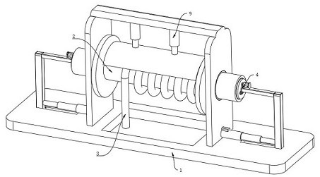
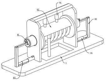
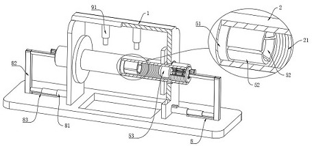
[0031] see Figure 1-7 , the present invention provides a technical solution: a ship anchoring device with an automatic locking function, including a mounting frame 1, a chain roller 2 rotatably arranged on the mounting frame 1, and a chain main body 3 wound on the outside of the chain roller 2 , the installation frame 1, the anchor chain roller 2 and the anchor chain main body 3 are all existing common structures, and will not be described in detail here;

...


PUM


Abstract

The invention discloses a ship anchoring device with the automatic locking function, which comprises a mounting frame, an anchor chain roller rotationally arranged on the mounting frame and an anchor chain body wound on the outer side of the anchor chain roller, the anchor chain roller is of a hollow circular pipeline structure, and internal threads are formed in the inner walls of the two sides of the anchor chain roller correspondingly; the ship anchoring device with the automatic locking function is different from the prior art, after the anchor chain roller rotates by a specified number of turns, releasing of the anchor chain body is stopped, the situation that the anchor chain body is overall disengaged due to continuous increasing of the releasing speed is avoided. Meanwhile, the anchor chain body is prevented from being separated from the anchor chain body. The releasing length of the anchor chain body can be obtained by calculating the releasing length of the anchor chain body when the anchor chain roller rotates to stop at a single time and the number of times of reciprocating work, and in addition, the position of the anchor chain body can be locked in real time through the limiting effect of the auxiliary locking piece on the anchor chain body.

Description

technical field [0001] The invention relates to the technical field of ship anchoring equipment, in particular to a ship anchoring device with an automatic locking function. Background technique [0002] When the ship encounters wind and waves or has to turn at a large angle, it needs to carry out anchoring operations. The anchor chain with the anchor is lowered to the seabed through the windlass and the chain stopper, and the forward and backward movement of the ship is restricted by the anchor's grip on the seabed. The ship reduces the degree of turbulence in the wind and waves or makes a circular motion with the anchor as the center of the circle and the anchor chain as the radius to achieve a large-angle turn. Generally, when anchoring, the top flow is the principle. The ship approaches the anchor position slowly against the wind or top flow, and stops in time. Reverse, drop the anchor in a slight backward or forward inertia, loosen the anchor chain, and make the anchor ...

Claims


Application Information

Patent Timeline
Patent Type & Authority Applications(China)
IPC IPC(8): B63B21/18B63B21/22
CPCB63B21/18B63B21/22
Inventor 马文耀孙墨林
Owner GUANGDONG OCEAN UNIVERSITY
Learn More