Cold and hot double-mixing blast furnace liquid slag cutting and crushing device
A crushing device, liquid slag technology, applied in recycling technology, grain processing, etc., can solve the problems of poor recycling efficiency, environmental pollution, large water consumption, etc., and achieve the effect of good cooling efficiency
- Summary
- Abstract
- Description
- Claims
- Application Information
AI Technical Summary
Problems solved by technology
Method used
Image

Examples
Embodiment 1
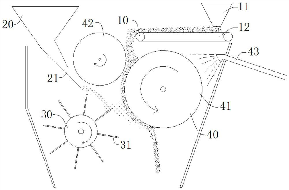
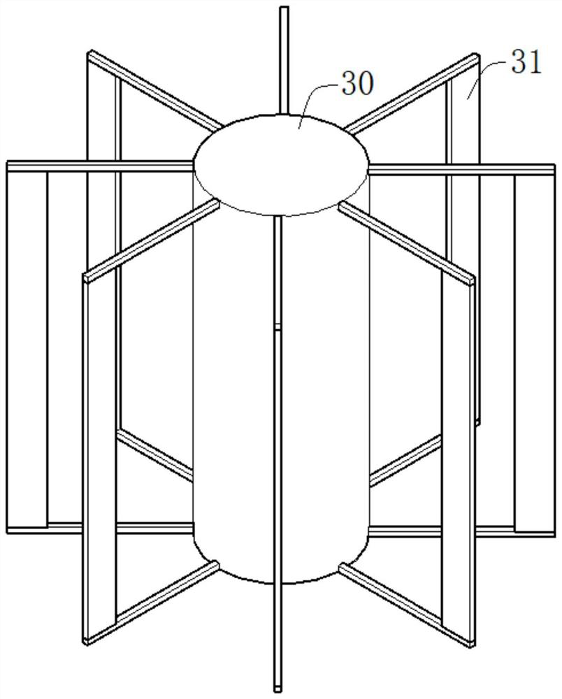
[0035] Such as figure 1 and figure 2 As shown, a cutting and crushing device for liquid slag of a cold and hot double-mixed blast furnace in this embodiment includes a cold slag feeding mechanism 10, a hot slag feeding mechanism 20, a cutting and crushing mechanism 30, and a solidification heat exchange mechanism 40. The cold slag feeding mechanism 10 is located above the solidification heat exchange mechanism 40 , the cold slag feeding unit 10 includes a feeding hopper 11 and a cold slag conveying belt 12 , and the hot slag feeding mechanism 20 is located above the cutting and crushing mechanism 30 . The continuous hot slag flow is cut and segmented by the cutting and crushing mechanism 30, and then the liquid slag is centrifugally crushed by the high-speed rotation of the cylinder. The crushed blast furnace slag collides with the cold slag falling from the solidification heat exchange mechanism 40 and the cold slag on the surface of the solidification heat exchange drum to...
Embodiment 2
[0043]This embodiment is basically the same as Embodiment 1, the difference is that the solidification heat exchange mechanism 40 includes two solidification heat exchange rollers 41, and the two solidification heat exchange rollers are alternately placed obliquely above the cutting and crushing mechanism, one of which is the same as that of the embodiment 1 Place the same position, another roller is placed under it, the additional roller is mainly to prevent the wall sticking phenomenon caused by hot slag sputtering due to poor coordination between the amount of hot slag and the speed. When the rotating speed is too fast or too slow, the crushing angle of the liquid slag becomes larger, and the additional roller can effectively block it and perform solidification and heat exchange to prevent the slag from polluting the equipment.
Embodiment 3
[0045] This embodiment is basically the same as Embodiment 1, the difference is that a slag scraper will be provided on the right side of the solidification heat exchange drum 41, and the additional slag scraper is mainly for a small amount of penetrating through the cold slag layer and sticking to the wall of the drum The liquid slag is scraped off. When the high-temperature liquid slag is centrifuged by the cutting and crushing mechanism, the speed is too fast, causing the slag particles to penetrate the cold slag layer, which will affect the continuous operation of the equipment. for the continuous operation of the overall equipment.
PUM
 Abstract
Description
Claims
Application Information
 - R&D
- Intellectual Property
- Life Sciences
- Materials
- Tech Scout
- Unparalleled Data Quality
- Higher Quality Content
- 60% Fewer Hallucinations
Browse by: Latest US Patents, China's latest patents, Technical Efficacy Thesaurus, Application Domain, Technology Topic, Popular Technical Reports.
© 2025 PatSnap. All rights reserved.Legal|Privacy policy|Modern Slavery Act Transparency Statement|Sitemap|About US| Contact US: help@patsnap.com