
Method and system for determining running track of vehicle

A technology for running trajectories and vehicles, which is applied in image data processing, instrumentation, surveying and mapping, and navigation. Avoiding structural constraints, the effect of accurate and precise running trajectories of plane feature points and boundary feature points

Pending Publication Date: 2021-11-05
BEIJING JINGDONG QIANSHITECHNOLOGY CO LTD
View PDF1 Cites 0 Cited by
  • Summary
  • Abstract
  • Description
  • Claims
  • Application Information

AI Technical Summary

Problems solved by technology

However, although the point cloud matching algorithm is used to calculate the pose difference of adjacent frames, although the implementation is simple, the application scene has limitations, and there are the following disadvantages: 1) Based on the boundary feature points and plane feature points extracted from two adjacent frames Separate matching calculations have relatively high structural requirements for the environment area; 2) When there are unstructured scenes such as trees or grass in the environment area, it is difficult to extract high-precision boundary feature points and planes from adjacent frames Feature points; 3) During the matching process, the noise of the cloud point data of adjacent frames will participate in the entire matching operation, resulting in a large error in the pose difference of adjacent frames of the sensor obtained by the matching operation
When the environmental area is limited, the calculation error is relatively large, even if the closed-loop detection algorithm is used to correct it, the error cannot be completely eliminated
Therefore, based on the pose difference of the adjacent frames of the sensor, the error of the determined vehicle trajectory is relatively large, and it is impossible to accurately locate the vehicle or / and obtain a high-precision point cloud map

Method used


Image

  • Method and system for determining running track of vehicle
  • Method and system for determining running track of vehicle
  • Method and system for determining running track of vehicle

Examples


Embodiment Construction

[0043] The following will clearly and completely describe the technical solutions in the embodiments of the application with reference to the drawings in the embodiments of the application. Apparently, the described embodiments are only some, not all, embodiments of the application. Based on the embodiments in this application, all other embodiments obtained by persons of ordinary skill in the art without making creative efforts belong to the scope of protection of this application.

[0044]The terms "first", "second", "third", "fourth", etc. (if any) in the description and claims of the present invention and the above drawings are used to distinguish similar objects, and not necessarily Used to describe a specific sequence or sequence. It is to be understood that the data so used are interchangeable under appropriate circumstances such that the embodiments of the invention described herein are, for example, capable of practice in sequences other than those illustrated or desc...


PUM


Abstract

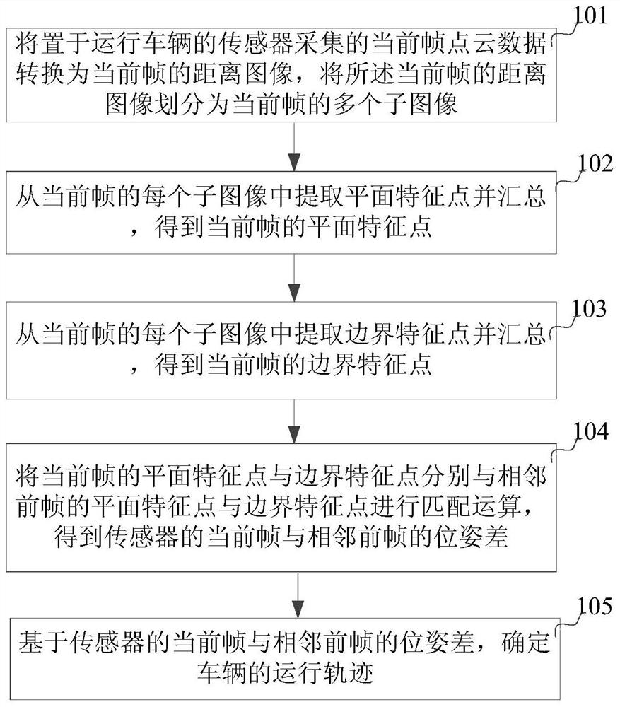
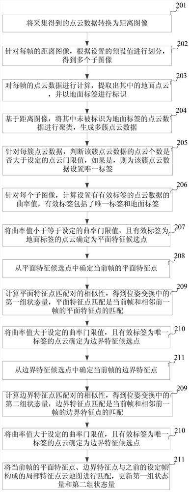
The invention discloses a method and system for determining a running track of a vehicle, and the method comprises the steps: converting the point cloud data of a current frame collected by a sensor disposed in a running vehicle into a distance image of the current frame, and dividing the distance image of the current frame into a plurality of sub-images of the current frame; summarizing the plane feature points extracted from each sub-image of the current frame to obtain the plane feature points of the current frame; collecting the boundary feature points extracted from each sub-image of the current frame to obtain the boundary feature points of the current frame; and performing matching operation on the plane feature points and the boundary feature points of the current frame and the plane feature points and the boundary feature points of the adjacent previous frame to obtain a pose difference between the current frame and the adjacent previous frame of the sensor, and determining a running track of the vehicle based on the pose difference. Therefore, according to the embodiment of the invention, the running track of the vehicle is accurately determined under the condition that an environment area is not limited.

Description

technical field [0001] The invention relates to artificial intelligence technology, in particular to a method and system for determining the running track of a vehicle. Background technique [0002] With the development of artificial intelligence technology and Internet of Things technology, unmanned vehicle technology has become the direction of technological development. The operation and implementation process of unmanned vehicles is as follows: first, sensors such as multi-line lasers or cameras are placed on the running vehicle, and the point cloud data of each frame is collected in units of image frames; then, based on adjacent frames Point cloud data, using the combination of point cloud matching algorithm and closed-loop detection algorithm to calculate the pose difference of the adjacent frames of the sensor, that is, the cumulative odometer of the adjacent frames of the sensor; finally, due to the relative distance between the sensor and the vehicle The position i...

Claims


Application Information

Patent Timeline
Patent Type & Authority Applications(China)
IPC IPC(8): G06T7/73G06K9/00G06K9/34G06K9/46G06K9/62G01C21/00
CPCG06T7/73G01C21/00G06T2207/10028G06T2207/30241G06F18/22
Inventor 王帅
Owner BEIJING JINGDONG QIANSHITECHNOLOGY CO LTD
Learn More