Optical imaging lens

An optical imaging lens, imaging surface technology, applied in optics, optical components, instruments, etc., can solve problems such as small selfie field of view

Active Publication Date: 2021-11-05
ZHEJIANG SUNNY OPTICAL CO LTD
View PDF0 Cites 2 Cited by
  • Summary
  • Abstract
  • Description
  • Claims
  • Application Information

AI Technical Summary

Problems solved by technology

[0004] The main purpose of the present invention is to provide an optical imaging lens to solve the problem that the mobile phone lens has a small Selfie field of view in the prior art

Method used


Image

  • Optical imaging lens
  • Optical imaging lens
  • Optical imaging lens

Examples


Embodiment 1

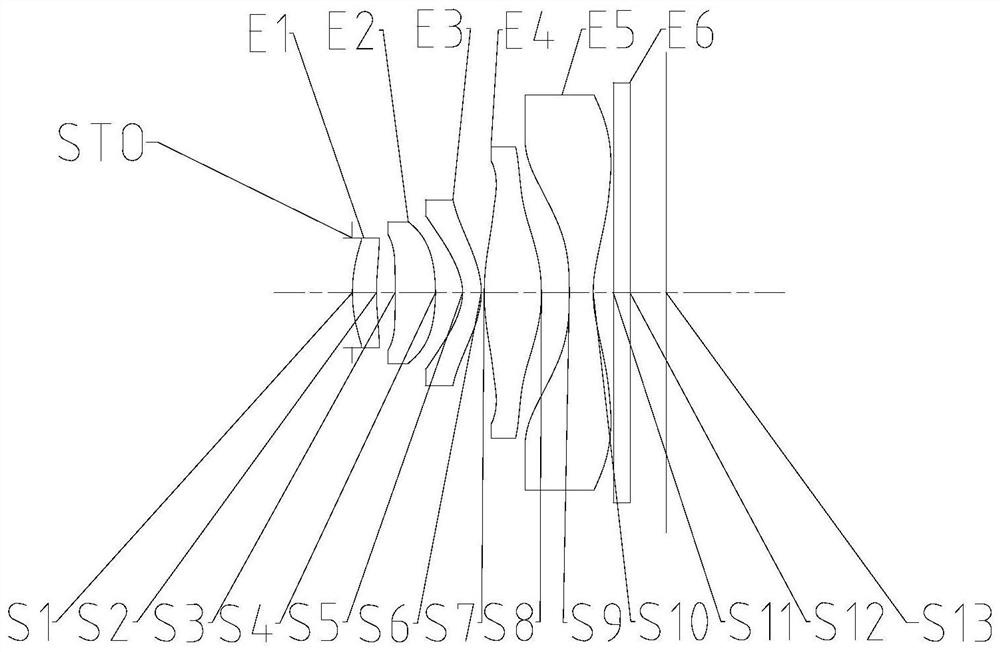
[0063] Such as Figure 1 to Figure 30 As shown, along the object side of the optical imaging lens to the image side of the optical imaging lens, the diaphragm, the first lens, the second lens, the third lens, the fourth lens and the fifth lens are included in sequence; the first lens has a positive refractive power The second lens has positive refractive power; the object side of the fourth lens is a convex surface, and the image side of the fourth lens is a convex surface; wherein, the on-axis distance TTL from the object side of the first lens to the imaging surface of the optical imaging lens is related to the optical imaging Half of the diagonal length of the effective pixel area on the imaging surface of the lens ImgH satisfies: 1.2

[0064] By rationally allocating the focal power of each lens, it is beneficial to balance the aberration generated by the optical imaging lens and ...

Embodiment 2

[0083] Such as Figure 1 to Figure 30 As shown, along the object side of the optical imaging lens to the image side of the optical imaging lens, the diaphragm, the first lens, the second lens, the third lens, the fourth lens and the fifth lens are included in sequence; the first lens has a positive refractive power The second lens has positive refractive power; The object side of the fourth lens is a convex surface, and the image side of the fourth lens is a convex surface; Wherein, the effective focal length f of the optical imaging lens, the effective pixel area diagonal line on the imaging surface of the optical imaging lens The half of the length ImgH meets the maximum semi-FOV of the optical imaging lens: 1

[0084] By rationally allocating the focal power of each lens, it is beneficial to balance the aberration generated by the optical imaging lens and greatly increas...


PUM


Abstract

The invention provides an optical imaging lens. From the object side of the optical imaging lens to the image side of the optical imaging lens, the optical imaging lens comprises a diaphragm, a first lens with positive focal power, a second lens with positive focal power, a third lens, a fourth lens of which the object side surface is a convex surface, and of which the image side surface is a convex surface, and a fifth lens element; the on-axis distance TTL from the object side surface of the first lens to the imaging surface of the optical imaging lens and half ImgH of the diagonal line length of an effective pixel area on the imaging surface of the optical imaging lens meet the relational expression that 1.2 < TTL/ImgH < 1.5; and the maximum half field angle Semi-FOV of the optical imaging lens is greater than 45 degrees and less than 60 degrees. With the optical imaging lens adopted, the problem that a mobile phone lens is small in selfie view field in the prior art can be solved.

Description

technical field [0001] The present invention relates to the technical field of optical imaging equipment, in particular to an optical imaging lens. Background technique [0002] With the iterative update of smart electronic devices such as mobile phones, computers and tablets getting faster and faster, the market has higher and higher requirements for the camera functions of these products. In addition to requiring the lens to have good imaging quality, it is also required to maintain high resolution, large depth of field, and large aperture. In terms of front-facing lenses, more and more mobile terminals are beginning to use wide-angle lenses, so they can have a wider field of view when taking selfies, so as to solve the problem of people's lack of vision for selfies. [0003] That is to say, in the prior art, there is a problem that the field of view of the Selfie is small in the lens of the mobile phone. Contents of the invention [0004] The main purpose of the prese...

Claims


Application Information

Patent Timeline
Patent Type & Authority Applications(China)
IPC IPC(8): G02B13/00G02B13/18G02B13/06
CPCG02B13/0045G02B13/06G03B30/00
Inventor 侯璟张晓彬闻人建科戴付建赵烈烽
Owner ZHEJIANG SUNNY OPTICAL CO LTD
Why Eureka
Try Eureka