Rolling bearing three-dimensional dynamic rigidity testing device and testing method thereof

A technology of rolling bearings and test devices, which is applied in the direction of measuring devices, testing of mechanical components, testing of machine/structural components, etc. It can solve the problems affecting the test accuracy of bearing dynamic stiffness, integration, and ineffective simulation of dynamic radial and axial excitations, etc. question

Pending Publication Date: 2021-11-05
DALIAN POLYTECHNIC UNIVERSITY +1
View PDF4 Cites 1 Cited by
  • Summary
  • Abstract
  • Description
  • Claims
  • Application Information

AI Technical Summary

Problems solved by technology

[0005] In order to better test the stiffness of rolling bearings, relevant researchers have proposed a series of test devices. For static stiffness testing, patent CN 108132187 (a high-precision rolling bearing static stiffness testing device and method) uses a hydraulic system as the axial and The direct drive element applied by the radial load measures the axial and radial displacement through two inductance comparators. The above method can effectively test the axial and radial direction of the rolling bearing under the action of pure axial load, pure radial load and shaft-diameter combined load. Static stiffness, but cannot obtain the dynamic stiffness characteristics of the rotational state
For dynamic stiffness testing, patent CN 110631830 A (rolling bearing radial stiffness measuring device) uses bracket components, force loading components, bearing housings and measurement components to build a test bench and uses the obtained radial load and displacement data to test radial stiffness; patent CN 109855868 A (a dynamic testing method and testing equipment for axial stiffness of bearings) uses a designed rotating loading mechanism to apply an axial load, and uses a displacement sensor to detect the axial displacement of the bearing to test the axial stiffness; CN 108680357 A (a rolling bearing axial and radial comprehensive dynamic stiffness measuring device) are connected by the electric spindle and the transmission shaft, the test bearing is installed on the transmission shaft, the axial relative displacement of the inner and outer rings of the bearing is tested by the axial test device, and the radial direction of the inner and outer rings of the bearing is tested by the radial test device Relative displacement, and then collect the load analog and deformation analog of the sensor to test the radial stiffness and axial stiffness; most of the above-mentioned dynamic stiffness test methods are to calculate the load, on the one hand, the axial load is not accurately obtained, and in the actual operation process Bearing load has many influences, unbalance, misalignment, etc. will affect the load. In addition to the influence of amplitude, there is also frequency (1 times frequency of rotor, 2 times frequency, etc.) and so on. Therefore, only when the load is accurately obtained can the bearing dynamics be accurately calculated Stiffness, especially the amplitude corresponding to the frequency; on the other hand, the position of the inner ring of the bearing is represented by the equivalent method of shaft displacement, which will easily cause the vibration displacement of the bearing seat to be integrated into the vibration of the inner ring, affecting the actual displacement test. On the other hand, there is a certain offset distance between the installation position of the single sensor and the position of the inner ring of the bearing along the axis. The displacement test results will be due to the large difference between the translational and pitching movements of the rotor and the displacement of the actual inner ring of the bearing, which will affect Bearing Test Accuracy
[0006] On the other hand, most of the current bearing dynamic stiffness tests are in a stable load environment, and do not effectively simulate dynamic radial and axial excitations; in addition, some devices do not have the function of applying axial preload; The test accuracy of bearing dynamic stiffness will be affected by preload and dynamic radial load; at the same time, most test devices and methods cannot realize simulation under variable temperature, and cannot test dynamic stiffness under variable temperature environment;

Method used


Image

  • Rolling bearing three-dimensional dynamic rigidity testing device and testing method thereof
  • Rolling bearing three-dimensional dynamic rigidity testing device and testing method thereof
  • Rolling bearing three-dimensional dynamic rigidity testing device and testing method thereof

Examples


Embodiment Construction

[0040] The specific implementation manners of the present invention will be further described below in conjunction with the accompanying drawings and technical solutions.

[0041] It should be understood that the appended drawings are not to scale, presenting a suitably simplified representation of various features illustrative of the basic principles of the invention. The specific design features of the invention disclosed herein, including, for example, specific dimensions, orientations, locations and shapes will be determined in part by the particular intended application and use environment.

[0042] In the accompanying figures, the same or equivalent parts (elements) are designated with the same reference numerals.

[0043] In the description of the present invention, it should be noted that the terms "center", "longitudinal", "transverse", "upper", "lower", "front", "rear", "left", "right", " The orientations or positional relationships indicated by "vertical", "horizon...


PUM


Abstract

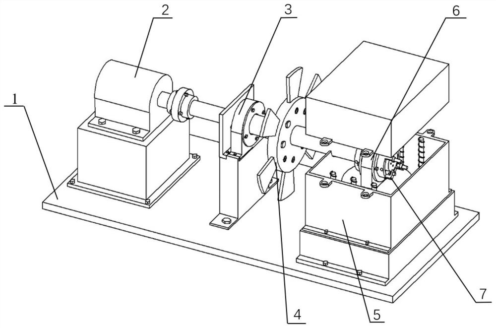
The invention relates to the field of rolling bearing rigidity testing, in particular to a rolling bearing three-dimensional dynamic rigidity testing device and a testing method thereof. The rolling bearing three-dimensional dynamic rigidity testing device comprises a base, a motor assembly, a bearing rotor system, a centrifugal load excitation device, an environment simulation testing box, a to-be-tested bearing device and a displacement testing device. The device is a bearing three-dimensional (axial, horizontal and vertical) dynamic rigidity testing device for obtaining a bearing dynamic accurate load and deformation displacement compensation based on three-way force sensing, and is simultaneously provided with a dynamic axial and radial excitation and axial static loading device, an environment temperature simulation device, and the dynamic rigidity of different types of bearings can be tested under the conditions of dynamic and static excitation and different temperatures.

Description

technical field [0001] The invention relates to the field of rolling bearing stiffness testing, in particular to a rolling bearing three-dimensional dynamic stiffness testing device and a testing method thereof. [0002] technical background [0003] The dynamic stiffness of rolling bearings is an important index to measure the dynamic performance of bearings, and is the basis for bearing design and optimization. However, in the process of testing dynamic stiffness, due to the unbalanced characteristics of the rotor caused by mass eccentricity, the centrifugal force generated by it is decomposed by force (parallelogram law) can be divided into vertical and horizontal directions, resulting in time-varying vertical and horizontal loads, resulting in changes in vertical and horizontal stiffness, coupled with alternating axial loads, changes in axial stiffness will affect the change in dynamic stiffness, so In order to obtain accurate dynamic stiffness data, it is necessary to te...

Claims


Application Information

Patent Timeline
IPC IPC(8): G01M13/045
CPCG01M13/045Y02T90/00
Inventor 温保岗燕敬祥张旭翟敬宇冯冰韩清凯
Owner DALIAN POLYTECHNIC UNIVERSITY
Why Eureka
Try Eureka