
Transmission gear shifting device

A gear switching and transmission technology, which is applied in the field of gear switching structures and transmission gear switching devices, and can solve the problems of needing a switching process, operation time, occupation, and high risk

Pending Publication Date: 2021-11-05
杨勇
View PDF2 Cites 0 Cited by
  • Summary
  • Abstract
  • Description
  • Claims
  • Application Information

AI Technical Summary

Problems solved by technology

[0006] The above two patents switch between the two operating conditions manually, which invisibly increases the complexity of the operation. It is necessary to manually slide the gear during driving, and it needs to be switched during operation when shifting gears, which requires an occupation of One hand is used to operate the gear shift, and the other hand is used to drive the handle, and during the switching process, a switching process and operation time are required. Since the electric tricycle is basically operated by the handle, when one hand leaves the operating handle, it needs Distract driving attention, divert part of attention to shifting, bring potential danger to vehicle driving, especially when climbing a hill, when it is necessary to switch gears due to insufficient power, the potential danger is even greater. , for some female drivers, it is necessary to pay a certain amount of switching arm strength, which brings a certain degree of difficulty to driving. How to realize the automatic switching of gears is a goal most sought by those skilled in the art

Method used


Image

  • Transmission gear shifting device
  • Transmission gear shifting device
  • Transmission gear shifting device

Examples


Embodiment Construction

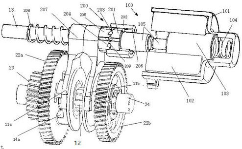
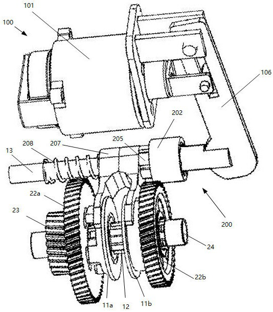
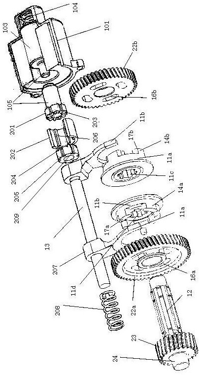
[0025] The technical solution of the present invention will be described in detail below in conjunction with the accompanying drawings. In the present invention, the connecting parts of the push-pull mechanism 100 and the rotating mechanism 200 can be connected by a connecting rod 105, or can be connected by a lever 106. The structures of other parts are exactly the same. Therefore, in the following description, except figure 2 In addition, it is mainly explained in the way of connecting rod structure.

[0026] A transmission gear switching device, including a shift fork, figure 1 It is a schematic diagram of the structure of the gear switching device of the connecting rod connection type transmission, figure 2 It is a schematic diagram of the gear switching device of a lever-connected transmission, image 3 It is a schematic diagram of an exploded structure of a link-connected transmission gear switching device. The transmission gear switching device includes a push-pu...


PUM


Abstract

The invention discloses a transmission gear shifting device and belongs to the field of electric vehicles. The shifting device comprises a push-pull mechanism, a rotating mechanism and a shifting mechanism, wherein the push-pull mechanism comprises a linear reciprocating motion mechanism and a connecting rod or a lever connected with the linear reciprocating motion mechanism; the rotating mechanism comprises a push-pull barrel and a shifting rotating barrel opposite to the push-pull barrel; fixing sleeves are arranged on the peripheries of the push-pull barrel and the shifting rotating barrel; and a motion decomposition mechanism is arranged on the inner circumference of the fixing sleeve, the motion decomposition mechanism transmits axial motion to the shifting fork and simultaneously performs circumferential rotation, the circumferential rotation changes the pause position of the axial motion, and the shifting rotating barrel pauses once at the starting point or the ending point of the axial motion every time the axial motion is performed, so that the shifting rotating barrel is shifted once between a low-speed gear and a high-speed gear. According to the transmission gear shifting device, the gear shifting mode can be simplified, the gear shifting speed is increased, the driving hidden danger in the vehicle driving process is reduced, and the vehicle driving safety is improved.

Description

technical field [0001] The invention relates to a gear switching structure, in particular to a transmission gear switching device, which belongs to the field of electric vehicles. Background technique [0002] As a vehicle with low energy consumption, no pollution, and convenient and fast movement, electric tricycles have been basically popularized in cities. In order to develop customers in hilly and mountainous areas, electric vehicle manufacturers have improved the shifting structure of electric vehicles. By shifting gears, it is possible to drive at high speed on flat roads or under no-load conditions, and to use high torque to move forward at low speeds under climbing or load conditions, which basically solves the problem of using electric vehicles in hills and mountains. There are two working conditions during the operation of the motor. When the vehicle needs to output a large torque, the forward speed can be reduced. In this case, it is suitable to use the low-speed ...

Claims


Application Information

Patent Timeline
IPC IPC(8): F16H63/32F16H63/30B62M25/08
CPCF16H63/32F16H63/3013F16H63/304F16H63/3023B62M25/08F16H2063/321Y02T10/62
Inventor 孙军李清宇胡一杰杨勇
Owner 杨勇
Learn More