
Circumferential array spiral groove piston anti-settling magnetorheological damper

A magnetorheological damper, circular array technology, applied in shock absorbers, shock absorbers, gas-liquid shock absorbers, etc., can solve the problem of affecting the damping performance and damping effect of shock absorbers. and application limitations, can not solve the problem of magnetorheological fluid settlement, etc., to avoid the decline of damping performance and vibration reduction effect, increase the adjustable range, and improve the settlement phenomenon.

Active Publication Date: 2022-06-21
CHONGQING UNIV
View PDF14 Cites 1 Cited by
  • Summary
  • Abstract
  • Description
  • Claims
  • Application Information

AI Technical Summary

Problems solved by technology

[0002] The rheological damper is a vibration damping device based on the magneto-rheological effect. It is widely used in various fields because of its adjustable damping force and semi-active control. However, due to the static settlement problem of the magnetorheological fluid, the magnetic The development and application of rheological dampers are greatly restricted
[0003] In the prior art, the problem of magnetorheological fluid settlement is usually solved by improving the material of the magnetorheological fluid itself, but the improvement of the magnetorheological fluid itself can only delay the sedimentation speed of the magnetorheological fluid, and cannot solve the problem of long-term storage. The settlement problem of the magnetorheological fluid; when the damper is left standing for a long time, the magnetorheological fluid will still settle, which will affect the damping performance and vibration reduction effect of the shock absorber

Method used


Image

  • Circumferential array spiral groove piston anti-settling magnetorheological damper
  • Circumferential array spiral groove piston anti-settling magnetorheological damper
  • Circumferential array spiral groove piston anti-settling magnetorheological damper

Examples


Embodiment Construction

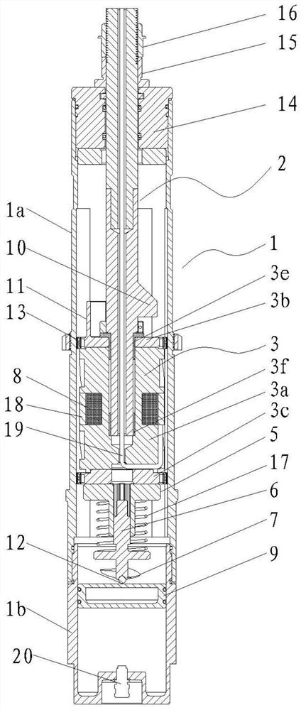
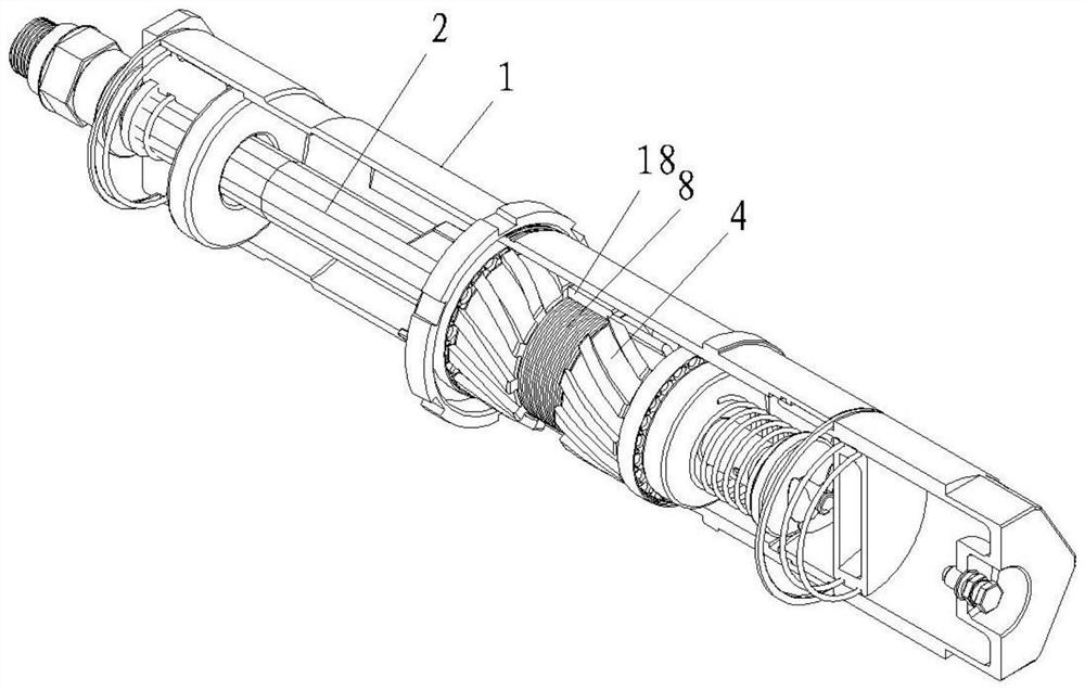
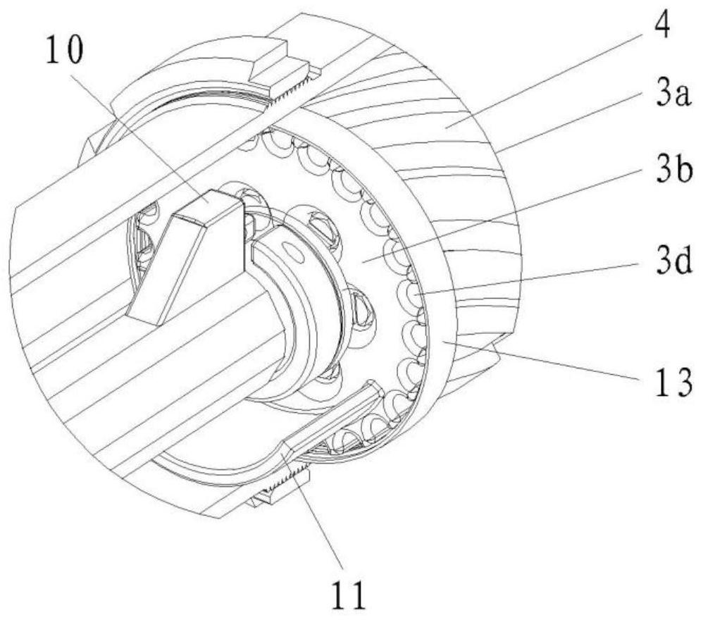
[0021] As shown in the figure: the circular array spiral groove piston anti-settling magnetorheological damper of this embodiment includes a piston cylinder 1, a piston rod 2 that is axially slidably fitted with the piston cylinder, and a piston assembly 3 connected to the piston rod. The piston assembly and the piston rod are rotatably matched with a single degree of freedom, the piston assembly and the inner circular surface of the piston cylinder are axially sealed, slidable and rotatably matched, the stirring assembly is in driving cooperation with the piston assembly, and the outer circular surface of the piston assembly is provided with a spiral Slot 4, the helical groove is connected to the axial end faces of the piston assembly, and when the piston rod drives the piston assembly to slide axially in the piston cylinder, the magnetorheological flow in the space located on both sides of the axial direction of the piston assembly in the piston cylinder The liquid flows thro...


PUM


Abstract

The invention discloses a circular array spiral groove piston anti-settling magneto-rheological damper, which comprises a piston cylinder, a piston rod and a piston assembly, the piston assembly and the piston rod rotate in a single degree of freedom, the piston assembly and the piston cylinder The circular surface axially seals and slides and rotates, and the stirring assembly is in transmission cooperation with the piston assembly. The outer surface of the piston assembly is provided with a spiral groove, and the spiral groove is connected to the two axial ends of the piston assembly. In the present invention, during the upward or downward process of the piston assembly, the magnetorheological fluid will exert a circumferential tangential component force on the piston assembly during the flow process, and then the entire piston assembly can be driven to rotate without external energy supply. Drive the stirring assembly to rotate and then stir the magnetorheological fluid to improve the settlement phenomenon of the magnetorheological fluid, so that the damper can quickly and automatically return to the normal working state in a short time after starting to work, thereby effectively avoiding the damping caused by the magnetorheological fluid settlement Problems with reduced performance and vibration damping.

Description

technical field [0001] The invention relates to the technical field of dampers, in particular to an anti-settling magnetorheological damper for a circular array spiral groove piston. Background technique [0002] The rheological damper is a vibration damping device based on the magnetorheological effect. Because of its adjustable damping force, it can be semi-actively controlled and widely used in various fields. The development and application of rheological dampers are greatly restricted. [0003] In the prior art, the problem of magnetorheological fluid sedimentation is usually solved by improving the material of the magnetorheological fluid itself, but the improvement of the magnetorheological fluid itself can only slow down the speed of the magnetorheological fluid sedimentation, and cannot solve the problem of long-term storage. When the damper is left standing for a long time, the magnetorheological fluid will still settle, which will affect the damping performance a...

Claims


Application Information

Patent Timeline
Patent Type & Authority Patents(China)
IPC IPC(8): F16F9/06F16F9/53F16F9/32F16F9/34
CPCF16F9/061F16F9/535F16F9/3214F16F9/3235F16F9/3221F16F9/34
Inventor 廖昌荣李嘉豪张永浩谢磊张红辉
Owner CHONGQING UNIV
Learn More