
Sliding rail hanging bracket plate for mounting mechanical automation equipment

A technology for automation equipment and installation, applied in mechanical equipment, mechanical conveyors, conveyors, etc., can solve problems such as labor-intensive, shaking, reducing service life, etc., to achieve the effect of fast and convenient operation, quick installation and disassembly

Inactive Publication Date: 2021-11-05
深圳市鑫顺康精密机械有限公司
View PDF0 Cites 0 Cited by
  • Summary
  • Abstract
  • Description
  • Claims
  • Application Information

AI Technical Summary

Problems solved by technology

[0003] However, when the existing hanger plate is connected to the slide rail, a large number of bolts and other parts need to be used, which is very troublesome to install, and when the automation equipment is placed directly on the hanger plate, multiple workers are required to protect the equipment, and then other workers Fixing the equipment by telescopic operation requires a lot of manpower, and the equipment may shake during transportation. Since the automation equipment is relatively precise, if the shaking is too large, the equipment will be damaged or the service life will be reduced.

Method used


Image

  • Sliding rail hanging bracket plate for mounting mechanical automation equipment
  • Sliding rail hanging bracket plate for mounting mechanical automation equipment
  • Sliding rail hanging bracket plate for mounting mechanical automation equipment

Examples


Embodiment Construction

[0024] The following will clearly and completely describe the technical solutions in the embodiments of the present invention with reference to the accompanying drawings in the embodiments of the present invention. Obviously, the described embodiments are only some, not all, embodiments of the present invention.

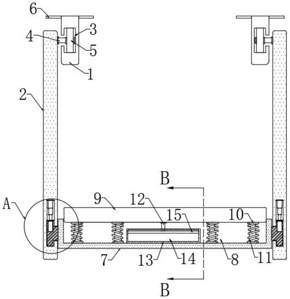
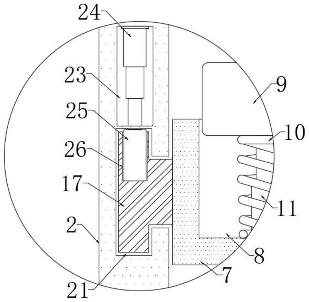
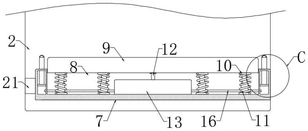
[0025] refer to Figure 1-5 A slide rail hanger plate for installing mechanical automation equipment, comprising two mounting plates 1, sliding grooves 3 are provided on the front sides of the two mounting plates 1, and connecting plates 2 are provided on the back sides of the two mounting plates 1 , a plurality of connecting rods 4 are installed on the opposite sides of the two connecting plates 2, each connecting rod 4 is equipped with a roller 5, and each roller 5 is slidingly connected with the corresponding sliding groove 3, and the two sliding grooves 3 are T-shaped grooves , each roller 5 is covered with anti-skid rubber, the roller 5 will not slip when moving...


PUM


Abstract

The invention discloses a sliding rail hanging bracket plate for mounting mechanical automation equipment. The sliding rail hanging bracket plate comprises two mounting plates, the front sides of the two mounting plates are provided with sliding grooves, the back sides of the two mounting plates are provided with connecting plates, the opposite sides of the two connecting plates are provided with a plurality of connecting rods, and each connecting rod is provided with a roller; and each roller wheel is slidably connected with the corresponding sliding groove, a movable plate is arranged between the two connecting plates, and a mounting groove is formed in the upper end of the movable plate. Compared with a traditional hanging bracket plate, the device is easier to disassemble and assemble, the equipment is more stable in the transportation process by arranging buffer springs, guide telescopic rods and other structures, internal parts of the equipment are prevented from being damaged due to shaking in the transportation process, meanwhile, by arranging a mounting box and other structures, when the equipment is placed, a stop lever can rise automatically, the equipment is prevented from slipping off when placed, and a connecting ring on the stop lever also facilitates further fixing of the equipment through a rope by a worker.

Description

technical field [0001] The invention relates to the technical field of slide rail hanger plates, in particular to a slide rail hanger plate for installing mechanical automation equipment. Background technique [0002] When installing mechanical automation equipment in a factory, it is often necessary to use hangers and other equipment to move the automation equipment to a designated location. The hanger moves through slide rails, fixes the automation equipment with ropes, and moves the equipment by using hanger plates and slide rails. , It is labor-saving to operate and convenient for the staff to carry; [0003] However, when the existing hanger plate is connected to the slide rail, a large number of bolts and other parts need to be used, which is very troublesome to install, and when the automation equipment is placed directly on the hanger plate, multiple workers are required to protect the equipment, and then other workers Fixing the equipment by telescopic operation re...

Claims


Application Information

Patent Timeline
Patent Type & Authority Applications(China)
IPC IPC(8): B65G35/00F16F15/067
CPCB65G35/00F16F15/067
Inventor 邓小军
Owner 深圳市鑫顺康精密机械有限公司
Learn More