Periodic motion control structure

A motion control and periodic technology, applied in the direction of manufacturing tools, grinding machine parts, metal processing equipment, etc., can solve the problems of inconvenient adaptation and control, inconvenient adjustment control, and inability to achieve the purpose of starting and stopping, so as to achieve convenient and cooperative start-up effects of stopping, satisfying regulatory tasks, and preventing immobility

Inactive Publication Date: 2021-11-05
崔丹龙
View PDF1 Cites 0 Cited by
  • Summary
  • Abstract
  • Description
  • Claims
  • Application Information

AI Technical Summary

Problems solved by technology

[0004] There is a phenomenon that it is not convenient to adjust and control the fixed period of the inner end, and the purpose of starting and stopping in a fixed position cannot be realized, which will cause certain inconvenience. At the same time, there is also a phenomenon that it is not convenient to carry out the adjustment and control of the inner end, which needs to be improved

Method used


Image

  • Periodic motion control structure
  • Periodic motion control structure
  • Periodic motion control structure

Examples


Embodiment Construction

[0029] The following will clearly and completely describe the technical solutions in the embodiments of the present invention with reference to the accompanying drawings in the embodiments of the present invention. Obviously, the described embodiments are only some, not all, embodiments of the present invention. Based on the embodiments of the present invention, all other embodiments obtained by persons of ordinary skill in the art without making creative efforts belong to the protection scope of the present invention.

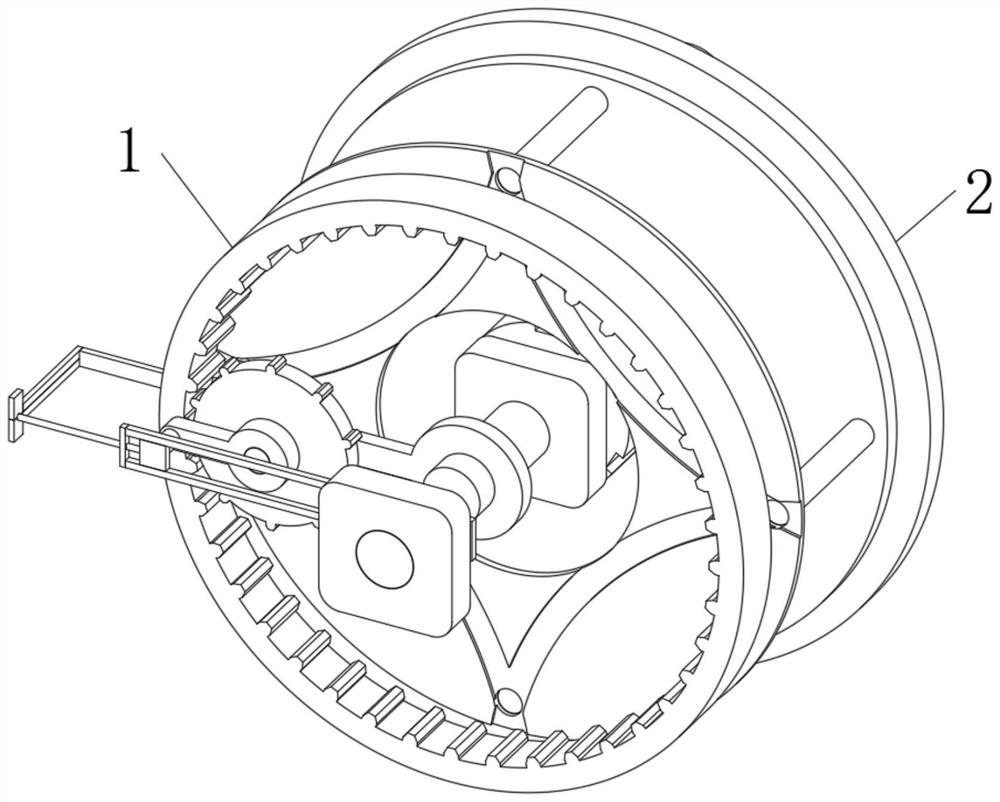
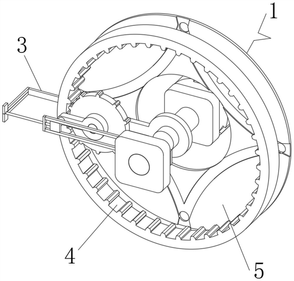
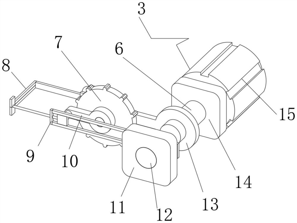
[0030] see Figure 1-6 , the present invention provides a technical solution: a periodic motion control structure, including a motion device 1, the rear end of the motion device 1 is movably connected with a push device 2, by installing the motion device 1, the inner end of the motion device 1 is limited by The limit connection part 3, the male gear plate 4 and the circuit plate 5 are composed of the limit connection part 3, which helps to limit the movement, ...


PUM


Abstract

The present invention discloses a periodic motion control structure. The periodic motion control structure comprises a motion device; the rear end position of the motion device is movably connected with a pushing device; the motion device comprises a limiting connection part, a male fluted disc and a circuit disc; the male fluted disc is arranged at the front position of the inner end of the motion device; the circuit disc is arranged at the rear end position of the male fluted disc; the upper end of the circuit disc is slidably connected with the limiting connection part; the limiting connection part comprises a transmission shaft, a matching fluted disc, a transmission structure, a frame plate frame, a first transmission shaft frame, a first stabilizing block, a stabilizing shaft frame, a second transmission shaft frame, a second stabilizing block and a motor; the motor is installed at the bottom of the inner end of the limiting connection part; the transmission shaft is inserted into the front end of the motor; and the center position of the transmission shaft penetrates through the center of the second stabilizing block. According to the periodic motion control structure, the purpose of inner end motion regulation and control is achieved through the arrangement of the motion device.

Description

technical field [0001] The invention relates to the technical field of mechanical equipment, in particular to a periodic motion control structure. Background technique [0002] According to Chinese Patent No. CN201922026851.4, the utility model discloses a mechanical arm motion control structure based on machine vision technology, including a grinding box, a swing arm and a grinding wheel. The top of the grinding box is provided with a feeding port, and the inside of the grinding box is fixed horizontally. A partition is connected, and the inside of the grinding box and below the partition are respectively provided with a feeding chamber and a swing chamber. The utility model drives the slider to slide in the chute of the swing arm through the drive of the motor, and then drives the swing arm to swing left and right, so that The grinding wheel can grind back and forth in the grinding tank. Due to the limited distance of the two stop pins, the push rod can only swing a relati...

Claims


Application Information

Patent Timeline
Patent Type & Authority Applications(China)
IPC IPC(8): B24B41/00
CPCB24B41/00
Inventor 崔丹龙
Owner 崔丹龙
Why Eureka
Try Eureka