
A battery charging system and integrated chip

A battery charging and voltage technology, applied in battery circuit devices, arrangement of multiple synchronous batteries, collectors, etc., can solve the problems of reducing work efficiency and achieve the effect of improving work efficiency and low power consumption

Active Publication Date: 2022-01-04
HALO MICROELECTRONICS CO LTD
View PDF0 Cites 0 Cited by
  • Summary
  • Abstract
  • Description
  • Claims
  • Application Information

AI Technical Summary

Problems solved by technology

[0005] However, since the current through the isolation switch is high, and the current will pass through the isolation switch when the system is charging and discharging, this will cause additional losses, thereby reducing the operating efficiency

Method used


Image

  • A battery charging system and integrated chip
  • A battery charging system and integrated chip
  • A battery charging system and integrated chip

Examples


Embodiment Construction

[0099] In order to make the purposes, technical solutions and advantages of the embodiments of the present application clearer, the technical solutions in the embodiments of the present application will be clearly and completely described below in conjunction with the drawings in the embodiments of the present application. Obviously, the described embodiments It is a part of the embodiments of this application, not all of them. Based on the embodiments in this application, all other embodiments obtained by persons of ordinary skill in the art without creative efforts fall within the protection scope of this application.

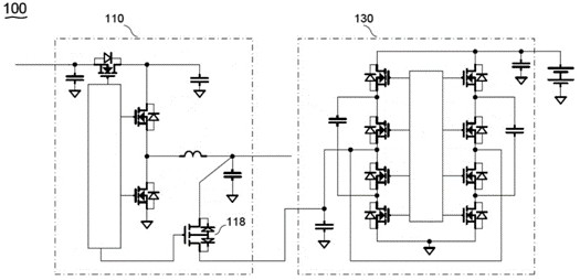
[0100] Please refer to figure 1 , figure 1 It is a schematic diagram of a circuit structure of a dual-stage charging system in the related art. Such as figure 1 As shown, the dual-stage charging system 100 includes two power-stage circuits, namely a first power-stage circuit 110 and a second power-stage circuit 130 .

[0101] Wherein, an isolation switch ...


PUM


Abstract

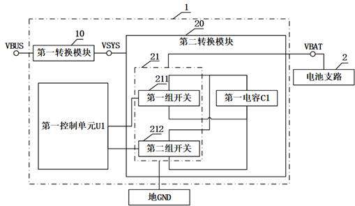
The application discloses a battery charging system and an integrated chip, which relate to the technical field of electronic circuits, wherein the battery charging system includes a first conversion module, a second conversion module and a first control unit, and the first conversion module is used to realize the first voltage The conversion between the voltage at the terminal and the voltage at the second voltage terminal. The second conversion module includes a first switch branch and a first capacitor, and the first switch branch includes a first group of switches and a second group of switches. The first control unit is respectively connected to the first group of switches and the second group of switches, the first control unit is used to turn on the first group of switches to establish a first conductive path, so as to charge the voltage across the first capacitor to The first preset voltage, and turning on the second group of switches to establish a second conductive path, so as to apply the sum of the voltage across the first capacitor and the system voltage to the third voltage terminal. Through the above method, the working efficiency of the battery charging system during the charging and discharging process of the battery can be improved.

Description

technical field [0001] The present application relates to the technical field of electronic circuits, in particular to a battery charging system and an integrated chip. Background technique [0002] With the further development of technology, various portable devices, such as mobile phones, tablet computers, digital cameras, MP3 players, etc., have become popular. Each portable device can use multiple rechargeable battery cells. Multiple rechargeable battery cells can be connected in series or parallel to form a rechargeable battery pack for storing electrical energy. [0003] Battery chargers are used to recover energy for multiple rechargeable battery cells. The battery charger is controlled to supply voltage (eg, constant voltage charging mode) and current (eg, constant current charging mode) to a plurality of rechargeable battery cells to restore energy to the battery. [0004] Since the battery capacity is limited, as the power consumption increases, it is necessary ...

Claims


Application Information

Patent Timeline
Patent Type & Authority Patents(China)
IPC IPC(8): H02J7/00
CPCH02J7/0013H02J7/00714H02J7/007182
Inventor 刘锐
Owner HALO MICROELECTRONICS CO LTD
Learn More