
Low-loss dry-type transformer

A dry-type transformer, low-loss technology, applied in transformer/inductor cooling, transformer/inductor core, transformer/inductor components, etc. Outer surface, adverse effects of transformer working efficiency, etc., to speed up air flow and exchange speed, improve heat dissipation effect, and reduce loss

Inactive Publication Date: 2021-11-02
泰顺永庆电力技术有限公司
View PDF0 Cites 2 Cited by
  • Summary
  • Abstract
  • Description
  • Claims
  • Application Information

AI Technical Summary

Problems solved by technology

[0004] Due to the working characteristics of transformers, dry-type transformers often generate a lot of heat when they work, so dry-type transformers are usually equipped with special cooling fans for cooling and heat dissipation during the working process of the transformers, but the cooling fans of existing dry-type transformers Usually, a cross-flow fan is installed before and after the dry-type transformer. The cross-flow fan generates longitudinal air flow to take away the heat generated by the transformer, thereby achieving the purpose of heat dissipation and cooling of the transformer. However, the cross-flow fan is generally installed at the bottom of the transformer. Moreover, the airflow generated by the cross-flow fan can only act on the outer surface of the high-voltage winding, which results in the low cooling efficiency of the cross-flow fan on the transformer. Even when the fan is running, the heat of the dry-type transformer will buildup that can adversely affect the overall efficiency of the transformer

Method used


Image

  • Low-loss dry-type transformer
  • Low-loss dry-type transformer
  • Low-loss dry-type transformer

Examples


Embodiment Construction

[0025] The following will clearly and completely describe the technical solutions in the embodiments of the present invention with reference to the accompanying drawings in the embodiments of the present invention. Obviously, the described embodiments are only some, not all, embodiments of the present invention. Based on the embodiments of the present invention, all other embodiments obtained by persons of ordinary skill in the art without creative efforts fall within the protection scope of the present invention.

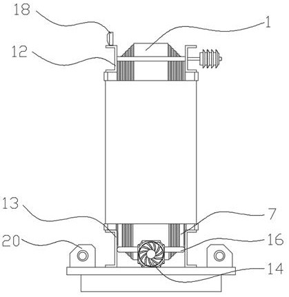
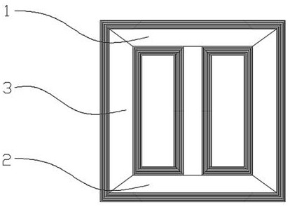
[0026] see Figure 1-6 As shown, the present invention is a low-loss dry-type transformer. Common dry-type transformers include single-phase transformers and three-phase transformers. Among them, three-phase transformers are more common. Dry-type transformers all include a multi-layer silicon steel sheet. A ferromagnetic core formed together, the ferromagnetic core includes upper and lower symmetrical upper iron yoke 1 and lower iron yoke 2 and at least one core co...


PUM


Abstract

The invention discloses a low-loss dry-type transformer which comprises a ferromagnetic core. The ferromagnetic core comprises an upper iron yoke, a lower iron yoke and at least one core column, the upper iron yoke and the lower iron yoke are vertically symmetrical, the core column extends between the two iron yokes, and a low-voltage winding packaged by epoxy resin is arranged on the periphery of the core column. A high-voltage winding packaged by epoxy resin is arranged on the periphery of the low-voltage winding, a cooling air channel is reserved between the low-voltage winding and the high-voltage winding, a plurality of air guide pipes are arranged in the cooling air channel at equal angles, and a plurality of air holes are formed in pipe bodies of the air guide pipes. One end of each air guide pipe is connected to an air extractor arranged outside the high-voltage winding, the air extractor is an exhaust fan, through the exhaust effect of the exhaust fan and the air guide pipes, the air flowing and exchanging speed in the cooling air channels is increased, hot air is actively exhausted out of the cooling air channels, the heat dissipation effect of the positions of the cooling air channels is improved, and the stable operation of the dry-type transformer is ensured.

Description

technical field [0001] The invention relates to the technical field of dry-type transformers, in particular to a low-loss dry-type transformer. Background technique [0002] Dry-type transformer is a kind of cooling by air convection, which is generally used for small-capacity transformers such as local lighting and electronic circuits. Simply put, dry-type transformer refers to a transformer whose iron core and winding are not immersed in insulating oil. [0003] Compared with oil-type transformers, dry-type transformers have no oil, so there are no problems such as fire, explosion, and pollution. Therefore, electrical codes and regulations do not require dry-type transformers to be placed in separate rooms. Therefore, dry-type transformers are widely used in local lighting, high-rise buildings, airports, wharf CNC machinery and equipment and other places. [0004] Due to the working characteristics of transformers, dry-type transformers often generate a lot of heat when t...

Claims


Application Information

Patent Timeline
IPC IPC(8): H01F27/08H01F27/24H01F27/26H01F27/30H01F27/32H01F27/40
CPCH01F27/085H01F27/2876H01F27/24H01F27/266H01F27/306H01F27/324H01F27/327H01F27/323H01F27/402H01F2027/406
Inventor 不公告发明人
Owner 泰顺永庆电力技术有限公司
Learn More