
Telescopic irradiation sample hole plug

A retractable and irradiated technology, applied in the field of nuclear power reactors, can solve the problems of inability to realize stable self-locking and plugging, and achieve the effect of simple structure, convenient operation and stable self-locking state

Pending Publication Date: 2021-11-02
NUCLEAR POWER INSTITUTE OF CHINA
View PDF0 Cites 0 Cited by
  • Summary
  • Abstract
  • Description
  • Claims
  • Application Information

AI Technical Summary

Problems solved by technology

[0004] The purpose of the present invention is to provide a retractable irradiated sample hole plug to solve the plugging problem caused by the inability of the irradiated sample hole plug used in the existing pressurized water reactor to realize stable self-locking

Method used


Image

  • Telescopic irradiation sample hole plug
  • Telescopic irradiation sample hole plug
  • Telescopic irradiation sample hole plug

Examples


Embodiment 1

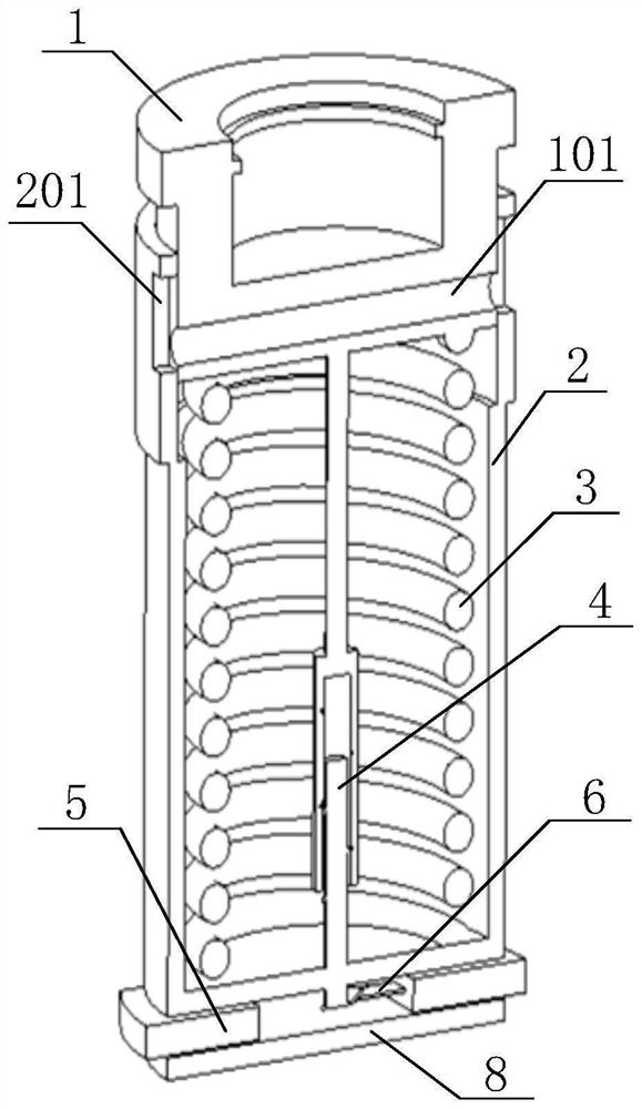
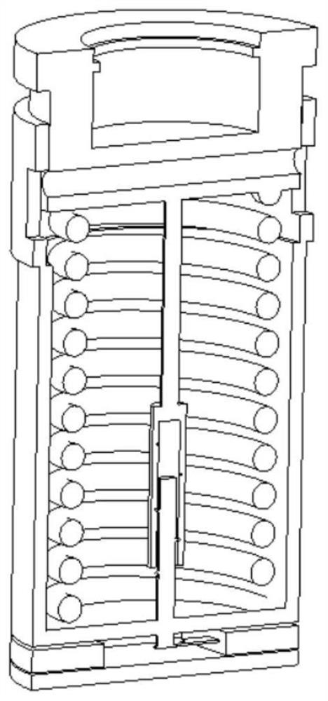
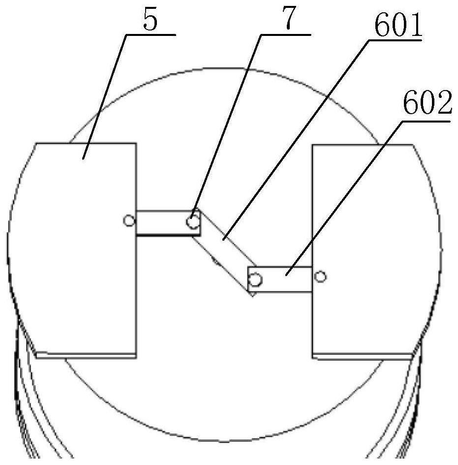
[0041] Such as Figure 1-Figure 4 As shown, a telescopic irradiation sample hole plug includes an upper end cover 1, a main body of the irradiation plug 2, an inner spring 3, a telescopic structure 4, a self-locking block 5, a "Z" type connector 6 and a lower bottom plate 8;

[0042] The irradiation plug main body 2 is a hollow structure with an open top, the upper end cover 1 is slidably arranged on the upper end of the irradiation plug main body 2, the lower bottom plate 8 is arranged below the irradiation plug main body 2, and the lower bottom plate 8 A cavity for accommodating the self-locking block 5 is formed between the bottom of the main body 2 and the irradiation plug body;

[0043] The upper end and the lower end of the inner cavity spring 3 are respectively connected with the bottom of the upper end cover 1 and the inner cavity bottom of the irradiation plug main body 2;

[0044] Both the self-locking block 5 and the "Z"-shaped connecting piece 6 are arranged in th...

Embodiment 2

[0054] Such as Figure 1-Figure 4 As shown, this embodiment is based on Embodiment 1. The upper side wall of the irradiation plug main body 2 is symmetrically provided with two limiting through grooves 201, and the limiting through grooves 201 are used to communicate with the inner surface of the irradiation plug main body 2. Cavity and external space, the side wall of the upper end cover 1 is provided with a limit block that cooperates with the limit channel 201, and the limit block protrudes from the limit channel 201 in the horizontal direction; the upper end cover 1 is provided with a through hole 101, the limit block is provided with a through groove, and the through hole 101 is communicated with the through groove.


PUM


Abstract

The invention discloses a telescopic irradiation sample hole plug which comprises an upper end cover, an irradiation plug main body, an intracavity spring, a telescopic structure, a self-locking block, a Z-shaped connecting piece and a lower bottom plate. The irradiation plug body is of a hollow structure with an opening in the top, the upper end cover is arranged at the upper end of the irradiation plug main body in a sliding mode, and the lower bottom plate is arranged below the irradiation plug main body. The upper end and the lower end of the intracavity spring are respectively connected with the bottom of the upper end cover and the bottom of the inner cavity of the irradiation plug main body. The self-locking block and the Z-shaped connecting piece are arranged in a cavity between the lower bottom plate and the irradiation plug main body. Self-locking of the self-locking block through rotation of the Z-shaped connecting piece. The telescopic structure comprises a threaded groove and a threaded rod, one end of the threaded rod is arranged in the threaded groove, the other end of the threaded rod penetrates through the bottom of the irradiation plug main body to be connected with a middle rod, and the upper end of the threaded groove is connected with the bottom of the upper end cover through a connecting rod. According to the invention, the problem of plug flushing caused by incapability of realizing stable self-locking of an irradiation sample hole plug adopted on an existing pressurized water reactor is solved.

Description

technical field [0001] The invention relates to the technical field of nuclear power reactors, in particular to a telescopic irradiation sample hole plug. Background technique [0002] During the normal operation of the widely used pressurized water reactor, it is necessary to detect the irradiated samples in the reactor at different working stages to ensure the working conditions in the reactor. In order to deal with this problem, it is necessary to use an irradiated sample holder placed in the reactor The sample material placed on the hanging basket cylinder and placed in the sample rack is the same as the normal working material in the reactor, so as to ensure that the working conditions of the reflected materials in the reactor can be accurately measured, so that the reactor can be tested in multiple stages. Correspondingly, a hole is made on the flange of the hanging basket corresponding to the position of the irradiated sample rack, so that the irradiated sample can be...

Claims


Application Information

Patent Timeline
Patent Type & Authority Applications(China)
IPC IPC(8): G21C19/02G21C17/10
CPCG21C19/02G21C17/10Y02E30/30
Inventor 何培峰王仲辉李燕罗英李浩于天达曹阳钟元章邓朝俊王庆田李娜胡雪飞王留兵饶琦琦张翼胡朝威蒋兴钧赵伟吴冰洁曹奇锋
Owner NUCLEAR POWER INSTITUTE OF CHINA
Learn More