Gas sensor working device and working method thereof
A gas sensor and working device technology, applied in the direction of material resistance, etc., can solve the problems of not effectively extending the service life of the sensor device, unable to meet the requirements of low power consumption, and unable to realize multi-point control, so as to improve the service life and improve the use. Longevity and Deterioration Reduction Effect
- Summary
- Abstract
- Description
- Claims
- Application Information
AI Technical Summary
Problems solved by technology
Method used
Image
Examples
Embodiment 1
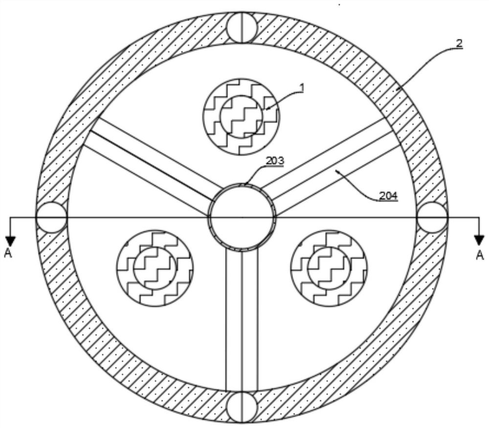
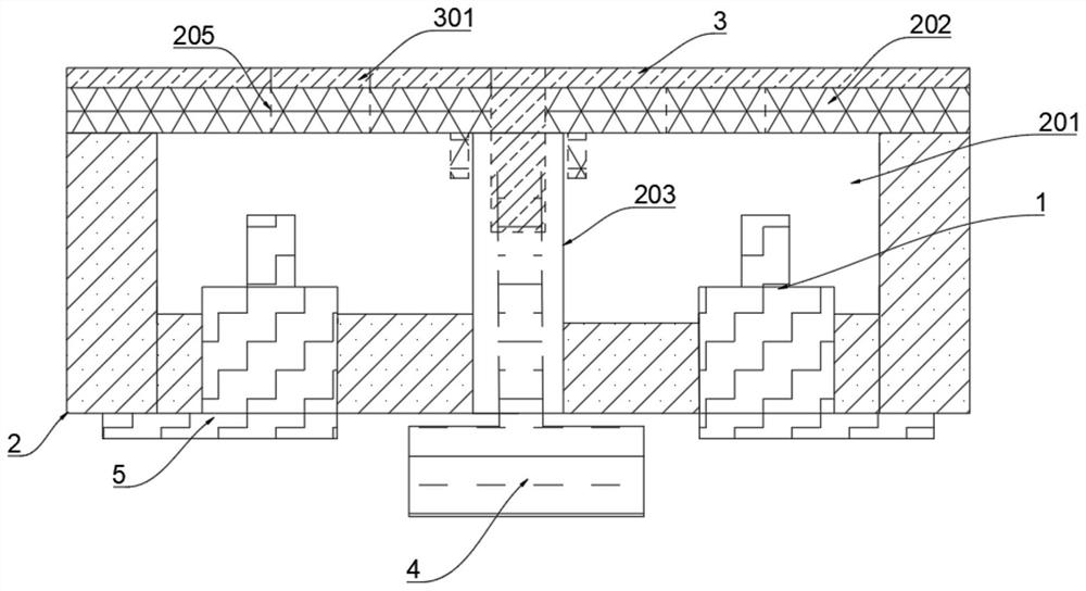
[0037] Such as figure 1 and figure 2 As shown, a gas sensor working device includes at least three sensors 1, wherein the sensor 1 includes at least one first sensor and at least two second sensors, a box body 2, an outer cover 3, a driving mechanism and a control circuit 5 , the driving mechanism is a motor 4, and the first sensor is used to calibrate the second sensor. The motor 4 and all the sensors 1 are connected with the control circuit 5 .
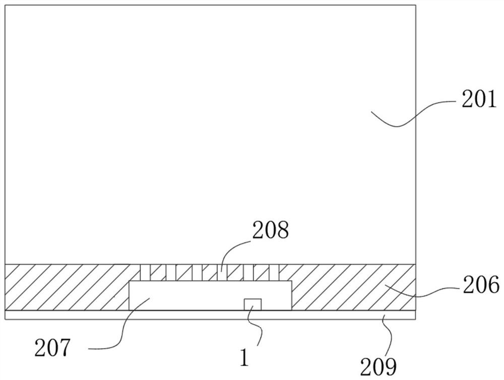
[0038] The inside of the box body 2 is evenly divided into at least three chambers 201, the inner cover 202 of the box body 2 is above the chamber 201, and at least one sensor 1 is arranged in each chamber 201, and one sensor in each chamber 201 1 is working, and other sensors 1 are in a silent state, that is, a low-frequency high-voltage pulse working state. At present, the second sensor is polluted, and other second sensors can be switched to work. These can be realized through the control circuit 5 . The position above each c...
Embodiment 2
[0046] Such as Figure 5 As shown, based on the working device provided by Embodiment 1 of the present invention, Embodiment 2 of the present invention provides the working method of the working device: when the second through hole 301 of the outer cover 3 is the first through hole 205 corresponding to the current second sensor When the positions overlap, the control circuit 5 controls the current second sensor to perform high-frequency and low-voltage pulse work, and the other second sensors perform low-frequency and high-voltage pulse work; when it is necessary to switch other second sensors to perform high-frequency and low-voltage work, the motor 4 drives the outer cover 3 to rotate At a preset angle, the second through hole 301 of the outer cover 3 coincides with the first through hole 205 facing one of the other second sensors, and the control circuit 5 controls one of the other second sensors to perform high-frequency and low-voltage pulse work. Taking three sensors 1 a...
Embodiment 3
[0051] Embodiment 3 of the present invention provides a specific example of the working method provided by Embodiment 2. The initial state during operation is that the second through hole 301 of the outer cover 3 is aligned with the first through hole 205 where one of the second sensors is located. The second sensor is in the working state and performs low-voltage pulses, the high level is 3.3V, the time is 500ms, the low level is 0, and the period is 5s. At this time, the other second sensor is in a silent state and is in a closed space. It performs a high-voltage pulse every 24 hours, the voltage is 6.4V, the power-on time is 30ms, and 7 days is a working period. The second sensor in the working state works for 7 days. The motor 4 rotates 120 degrees to allow the second sensor in the silent state to work, while the second sensor in the working state before enters the silent state. During the driving process of the motor 4, if the potential change of the second sensor in the ...
PUM
 Abstract
Description
Claims
Application Information
 - R&D Engineer
- R&D Manager
- IP Professional
- Industry Leading Data Capabilities
- Powerful AI technology
- Patent DNA Extraction
Browse by: Latest US Patents, China's latest patents, Technical Efficacy Thesaurus, Application Domain, Technology Topic, Popular Technical Reports.
© 2024 PatSnap. All rights reserved.Legal|Privacy policy|Modern Slavery Act Transparency Statement|Sitemap|About US| Contact US: help@patsnap.com


