
An oil-cooled hollow shaft structure

A shaft structure, cold hollow technology, applied in the field of oil-cooled hollow shaft structure, can solve the problems of failing to meet the requirements of lightweight design, increasing the dynamic unbalance value of the rotor, and reducing the NVH performance, so as to improve the NVH performance and reduce the dynamic Unbalanced effects, simple effects

Active Publication Date: 2022-05-31
HEFEI JUYI POWER SYST CO LTD
View PDF16 Cites 0 Cited by
  • Summary
  • Abstract
  • Description
  • Claims
  • Application Information

AI Technical Summary

Problems solved by technology

Among them, using the inner cavity of the hollow shaft as a part of the oil circuit is the mainstream structure, and its typical structure is as follows figure 1 As shown, the cooling oil enters the inner cavity of the rotating shaft from one end of the rotating shaft, collects inside the cavity, and then enters the oil passage inside the iron core through the radial hole of the rotating shaft under the action of high-speed centrifugal force, thereby achieving the effect of cooling the rotor, but this The structure has the following disadvantages: If only to meet the needs of oil delivery, if a small cavity is opened, the weight of the rotor will increase, which cannot meet the lightweight design requirements; if a large cavity is opened to meet the lightweight design, a large amount of oil inside the rotor will Aggregation; the dynamic unbalance value of the rotor is increased, and the oil surges during rotation, resulting in reduced NVH performance and increased torque fluctuations

Method used


Image

  • An oil-cooled hollow shaft structure
  • An oil-cooled hollow shaft structure
  • An oil-cooled hollow shaft structure

Examples


Embodiment Construction

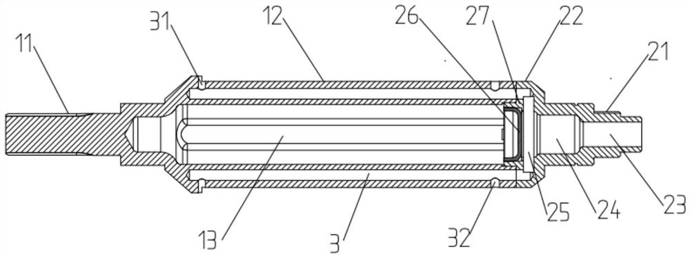
[0025] The second shaft end 21 is provided with an oil inlet 23 and a first inner cavity 24 that communicate with each other, and the second shaft body 22 is provided with a second inner cavity

[0027] During the processing, the first connecting portion 1 and the second connecting portion 2 can be formed by forging and then rough machining,

[0031] It should be understood that the above-described specific embodiments of the present invention are only used to illustrate or explain the present invention.


PUM


Abstract

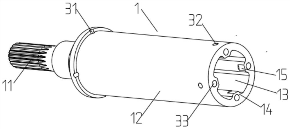
The invention discloses an oil-cooled hollow rotating shaft structure, which includes a first connecting part and a second connecting part, the first connecting part includes a connected first shaft end and a first shaft body, and the second connecting part includes a connected second shaft end and the second shaft body, the first shaft body and the second shaft body are sealed and connected to form the shaft body, the first connecting part is provided with a blind hole cavity, and the blind hole cavity opens to one side of the second connecting part, and the second shaft body The end is provided with a connected oil inlet hole and the first inner cavity, the second shaft body is provided with a second inner cavity, the second inner cavity communicates with the first inner cavity, and the end of the second shaft body is provided with a sealing plug , the sealing plug is used to separate the blind hole cavity and the second inner cavity, the shaft body is provided with an axial oil passage, the axial oil passage communicates with the second inner cavity, and the axial oil passage is also connected with the first oil passage hole and the second oil hole, the cooling oil flows out of the shaft body through the first oil hole and the second oil hole. The invention can effectively reduce the accumulation of oil inside the hollow rotating shaft structure under the premise of ensuring the lightweight design.

Description

An oil-cooled hollow shaft structure technical field [0001] The invention belongs to the technical field of motors, in particular to a kind of oil-cooled hollow shaft structure. Background technique [0002] As the power requirements of the motor are getting higher and higher, the heat dissipation requirements of the motor are gradually improved, and the heat dissipation mode of the motor is also has changed. It is a widely used solution to directly cool and dissipate the heat-generating components of the motor through cooling oil. The common oil circuit form of the front oil-cooled motor is as follows: after the external oil enters the motor, the first oil circuit is introduced into the casing, and passes through the oil on the casing. The oil passage or the oil injection hole cools the stator core and the end windings; the second oil passage enters the hollow shaft through the oil passage on the end cover The internal oil circuit, and then enter the internal oil cir...

Claims


Application Information

Patent Timeline
Patent Type & Authority Patents(China)
IPC IPC(8): H02K1/32H02K9/19F16C3/02F16H57/04
CPCH02K1/32H02K9/19F16C3/02F16H57/0417Y02T10/64
Inventor 范佳伦程勇顾杰李跃华
Owner HEFEI JUYI POWER SYST CO LTD
Learn More