Direct-driven variable-frequency permanent magnet motor of screw pump
A permanent magnet motor and screw pump technology, applied in pumps, pump components, electromechanical devices, etc., can solve problems affecting normal operation, permanent magnet direct drive variable frequency motor magnetic interference, etc., and achieve the effect of improving stability
- Summary
- Abstract
- Description
- Claims
- Application Information
AI Technical Summary
Problems solved by technology
Method used
Image

Examples
Embodiment 1
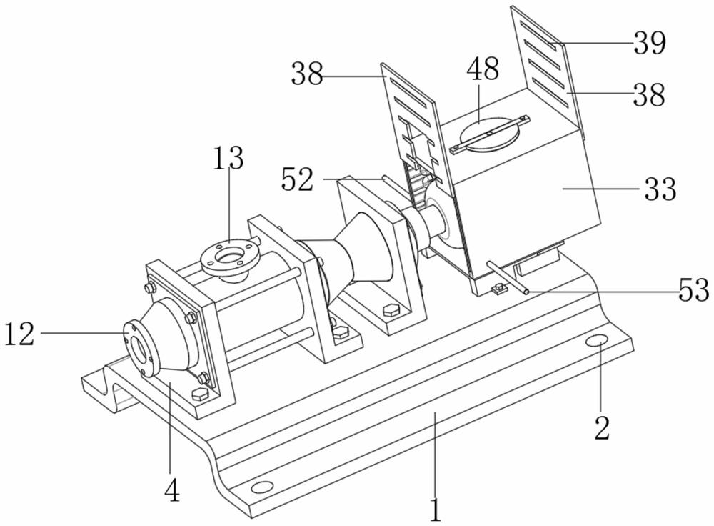
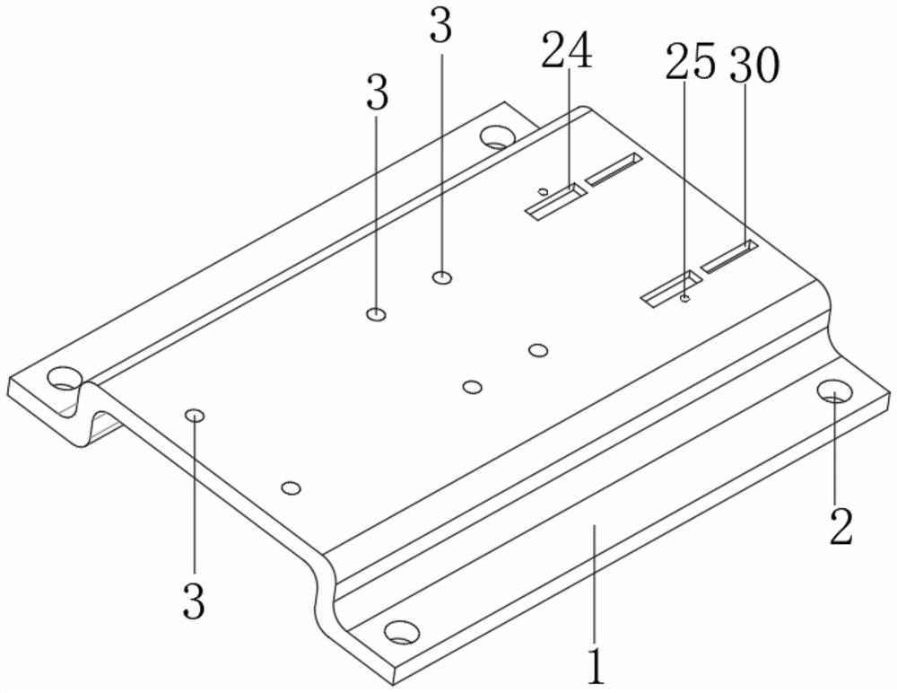
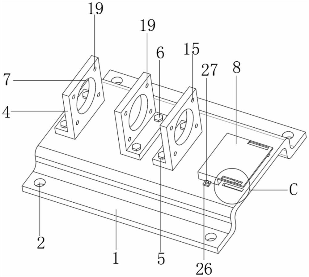
[0046] Such as figure 1 , figure 2 , image 3 , Figure 4 , Figure 5 with Image 6 As shown, the screw pump direct-drive variable frequency permanent magnet motor includes a base 1, the base 1 is a convex structure, four sets of connecting holes 2 are opened at the four corners of the top of the base 1, and the connecting holes 2 are set on the lower surface of the upper part of the base 1. In the upper four corners, there are three sets of mounting holes on the top of the base 1. The mounting holes are set on the surface of the upper part of the base 1 with a higher height. The two sets of mounting holes are symmetrically set on both sides of the center of the top of the base 1, and the other set of mounting holes are close to the base. 1 The top edge is set, each set of mounting holes includes two sets of mounting screw holes 3, the mounting screw holes 3 are set through the base 1, and the top of the base 1 is equipped with mounting components, the mounting components...
Embodiment 2
[0049] Embodiment 2 is a further improvement to Embodiment 1.
[0050] Such as figure 2 , image 3 , Figure 7 , Figure 8 , Figure 9 with Figure 10 as shown,
[0051] The top of the motor base 1 is symmetrically provided with two sets of penetrating moment grooves 29, and the top of the base 1 is matched with a positioning moment groove 30, and a protective component is arranged on the penetrating moment groove 29 and the positioning moment groove 30. The protective component includes a positioning screw hole 31, a positioning Plate 32, protective frame 33, positioning hole 34, positioning screw 35, chute 36, slide block 37, protective baffle 38, heat dissipation groove 39 and rectangular through groove 40; positioning screw hole 31 is arranged on the center of the inner wall of penetrating moment groove 29, The positioning plate 32 is plugged into the through moment groove 29 and the positioning moment groove 30, the top of the positioning plate 32 is flush with the...
Embodiment 3
[0053] Embodiment 3 is a further improvement to Embodiment 2.
[0054] Such as figure 1 , Figure 8 , Figure 9 , Figure 10 with Figure 11 As shown, the inside of the protective frame 33 is provided with a cooling assembly, and the cooling assembly includes a circular through hole 41, a fan 42, a connecting rod 43, a bar 44, a connecting screw 45, a locking hole 46, a matching locking hole 47, a locking Rod, circular arc plate 48, installation arc groove 49, circulating water pipe 50, connecting pipe 51, water inlet pipe 52 and water outlet pipe 53; circular through hole 41 is arranged at the center of the top of protective frame 33, horizontal bar 44 is fixedly set on connecting rod 43, the fan 42 rotates at the bottom of the connecting rod 43, the connecting screw 45 is threaded to connect the horizontal bar 44 and the protective frame 33, the locking hole 46 runs through the center of the side of the horizontal bar 44, and the locking hole 47 is set through the connec...
PUM
 Abstract
Description
Claims
Application Information
 - R&D
- Intellectual Property
- Life Sciences
- Materials
- Tech Scout
- Unparalleled Data Quality
- Higher Quality Content
- 60% Fewer Hallucinations
Browse by: Latest US Patents, China's latest patents, Technical Efficacy Thesaurus, Application Domain, Technology Topic, Popular Technical Reports.
© 2025 PatSnap. All rights reserved.Legal|Privacy policy|Modern Slavery Act Transparency Statement|Sitemap|About US| Contact US: help@patsnap.com