Rotation and lifting transmission mechanism of hosiery machine

A lifting drive mechanism and lifting transmission technology, which is applied in the field of hosiery machine rotation lifting transmission mechanism, can solve problems such as unstable work, inability to accurately locate the height of the gripping parts of socks, unstable lifting of the gripping parts, etc., and achieve the goal of solving the lifting accuracy Effect

Active Publication Date: 2021-10-29
SHAOXING CITY YUEFA MACHINE
View PDF9 Cites 0 Cited by
  • Summary
  • Abstract
  • Description
  • Claims
  • Application Information

AI Technical Summary

Problems solved by technology

[0002] During the sock production process, the hosiery machine needs to grab the knit and formed socks from the needle cylinder and transfer them to the device for sewing the toe of the sock. The traditional hosiery machine rotating and lifting mechanism cannot accurately position the height of the sock grabbing parts, and The instability of the lifting and lowering of the traditional sock grabbing parts will affect the sock grabbing parts to catch the socks
The transmission shaft and the guide shaft of the traditional hosiery machine rotating and lifting mechanism are not on the same straight line. When the motor or other actuators are working, the force is on the other side of the guide shaft, resulting in a large working load of the motor or other actuators, which is easy to cause the guide shaft to be stuck. dead, unstable at work

Method used


Image

  • Rotation and lifting transmission mechanism of hosiery machine
  • Rotation and lifting transmission mechanism of hosiery machine
  • Rotation and lifting transmission mechanism of hosiery machine

Examples


Embodiment Construction

[0028] Refer Figures 1 to 7 DETAILED DESCRIPTION OF THE PREFERRED EMBODIMENTS

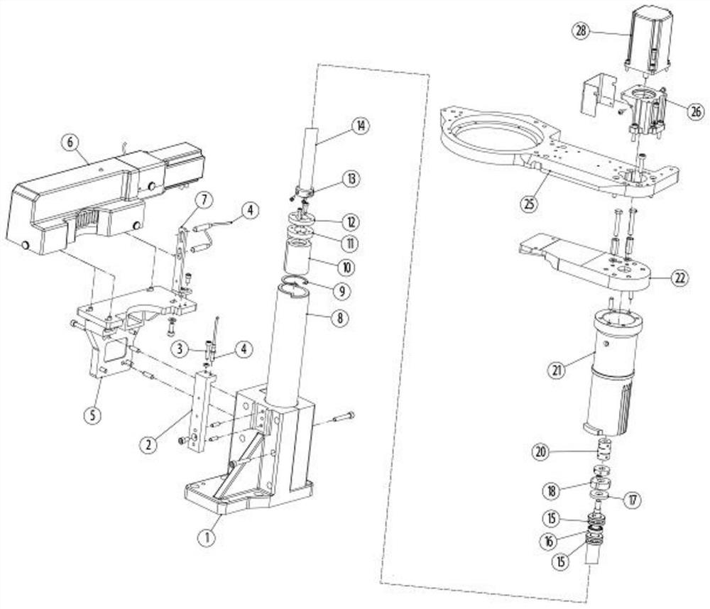
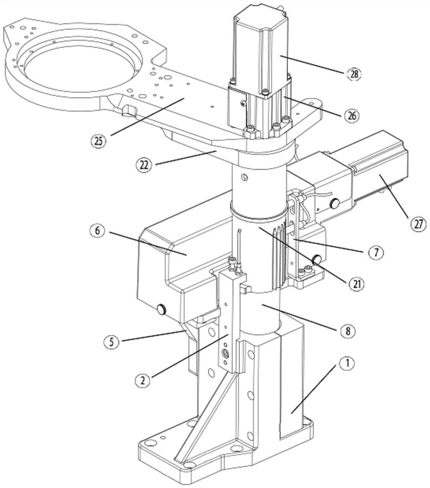
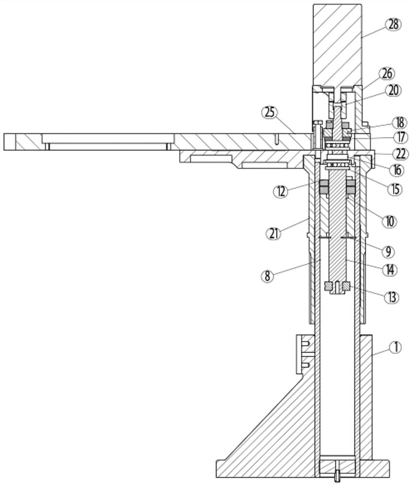
[0029] A sock machine rotation lifting drive mechanism, reference figure 1 with figure 2 The structure is shown, including a base 1, and a guide shaft 8 is mounted on the base 1, and the guide shaft 8 is provided with a transfer gear 21, and the upper end of the transfer tooth 21 is connected to a swing arm 25, said A transfer mechanism 6 that drives the transfer gear 21 rotation is provided on one side of the pedestal 1, which is provided with a lifting drive mechanism that controls the transfer gear 21 lifting down, and is disposed on the base 1 There is a sensing device 4 that feeds back the transfer tooth 21.

[0030] The swaying arm 25 is provided with a sock, and the transfer gear 21 can move up and down in the guide shaft 8 under the action of the lifting drive mechanism, the transfer mechanism 6 on the side controls the transfer tooth 21 rotation, transfer the cos 21 and the swing arm 25. The f...


PUM


Abstract

The invention discloses a rotation and lifting transmission mechanism of a hosiery machine. The mechanism comprises a base; a guide shaft is installed on the base; a transfer tooth cylinder is arranged outside the guide shaft in a sleeving mode; the upper end of the transfer tooth cylinder is connected with a swing arm; a transfer mechanism for driving the transfer tooth cylinder to rotate is arranged on one side of the base; a lifting driving mechanism for controlling the transfer tooth cylinder to ascend and descend is arranged above the swing arm; and a sensing device for feeding back the position of the transfer tooth cylinder is arranged on the base. Lifting and rotation control of a grabbing part of the hosiery machine can be achieved, and the sensing device is arranged to feed back whether the grabbing part is in place or not, so that the problem of lifting precision is effectively solved; and the lifting driving mechanism and the guide shaft are located on the same straight line, so that the defects that a transmission shaft and a guide shaft of a traditional structure are not located on the same straight line, the work load is relatively large, and consequently the guide shaft is stuck and work is unstable are overcome.

Description

Technical field [0001] The present invention relates to the technical field of knitting machinery, and more particularly to a sock machine rotation lifting drive mechanism. Background technique [0002] During the production of socks, the socks should be sewn on the socks of the stitching socks during the production process of socks, and the traditional socks rotating the lifting mechanism cannot accurately locate the height of the socks. The lifting of traditional socks grasping parts will not stabilize the socks to grab the part to grab the socks. Traditional socks rotating lifting mechanisms The drive shaft and the guide shaft do not work on the same line, the motor or other actuator work, and the force is on the other side of the guide shaft, causing the motor or other actuator to operate a large load, easy to make the guide shaft card Dead, it is very unstable when working. Inventive content [0003] In response to the deficiencies of the prior art, the present invention pr...

Claims


Application Information

Patent Timeline
Patent Type & Authority Applications(China)
IPC IPC(8): D04B15/94D04B9/46
CPCD04B15/94D04B9/46
Inventor 钱福海吴华盛陈宁单向海
Owner SHAOXING CITY YUEFA MACHINE
Why Eureka
Try Eureka