Chemical fiber filament post-processing system with diversified winding and use method

A chemical fiber and filament technology, which is applied in the field of chemical fiber filament post-processing system, can solve the problems of disrupting production continuity and occupying a large space, and achieve the effects of small space occupation, smooth operation and small volume

Active Publication Date: 2021-10-29
WUHAN TEXTILE UNIV
View PDF7 Cites 0 Cited by
  • Summary
  • Abstract
  • Description
  • Claims
  • Application Information

AI Technical Summary

Problems solved by technology

[0005] The purpose of the present invention is to overcome the defects and problems existing in the prior art that occupy a large space and disrupt production continuity, and provide a chemical fiber filament post-treatment that occupies a small space and can ensure production continuity with diverse windings System and method of use

Method used


Image

  • Chemical fiber filament post-processing system with diversified winding and use method
  • Chemical fiber filament post-processing system with diversified winding and use method
  • Chemical fiber filament post-processing system with diversified winding and use method

Examples


Embodiment 1

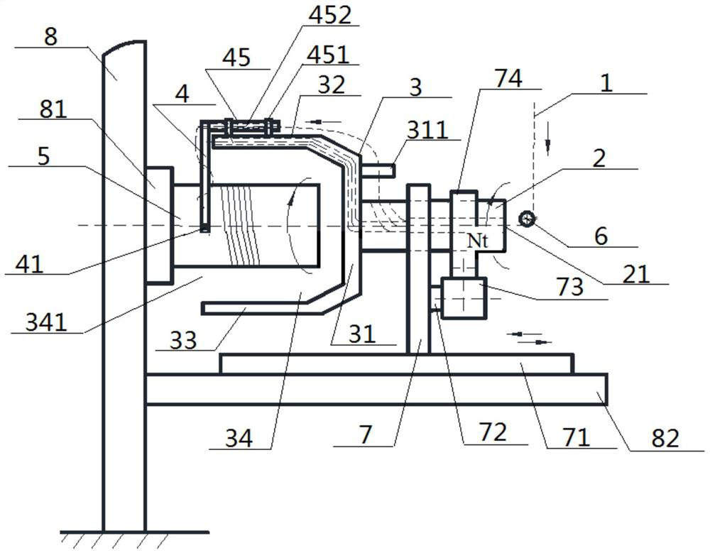
[0057] see figure 1 — Figure 8 , a post-processing system for chemical fiber filaments with various windings, the post-processing system includes a wire drum 5, a guide rod 4, a rotating pin 45, a twisting frame 3 and a rotor 2, and the twisting frame 3 includes a drive The rod 31, the screw rod 32 and the auxiliary rod 33, the two ends of the driving rod 31 are respectively connected with the inner ends of the screw rod 32 and the auxiliary rod 33. The driving rod 31, the screw rod 32 and the auxiliary rod 33 are surrounded by a total of One end of the wire drum 5 is arranged inside the frame inner cavity 34, and the other end of the wire drum 5 passes through the cavity opening 341 of the frame inner cavity 34 and extends to the end of the frame inner cavity 34. Externally, the outer side of the middle part of the driving rod 31 is connected with the inner end of the rotor 2, the outer end of the rotor 2 extends outward, and one end of the wire drum 5 is arranged opposite ...

Embodiment 2

[0060] The basic content is the same as that of Example 1, except that:

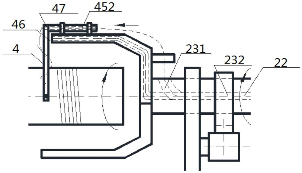
[0061] Structurally: the inside of the rotating pin 45 is provided with a coaxial pin shaft hole 452, and the inside of the connecting part of the guide screw 4 with the rotating pin 45 is provided with a rod shaft hole 47 that communicates with the pin shaft hole 452. .

[0062] Method: After the chemical fiber filament 1 is passed through the guide wire lumen 23 and the guide wire outlet hole 22 in sequence, the chemical fiber filament 1 travels in any of the following ways:

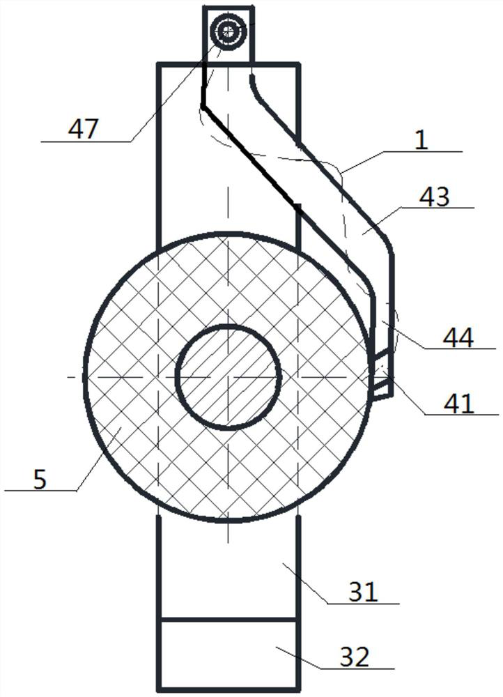
[0063] The first is to pass through the pin shaft hole 452 first, then pass through the rod shaft hole 47, and then wrap around the guide wire rod 4, then pass through the proximal guide wire hole 41, and wind it to the side of the wire cylinder 5 surround;

[0064] The second type is to wrap forward along the lead screw 32 first, then wrap around the lead screw 4 , then pass through the near-tube guide wire hole 41 , and wrap ...

Embodiment 3

[0066] The basic content is the same as that of Example 1, except that:

[0067]Structurally: the drive rod 31 is provided with a drive cavity 313, the screw rod 32 is provided with a wire cavity 321, and one end of the screw rod 32 close to the guide rod 4 is provided with a guide wire. The side of the rod 4 is facing the rod outlet 322 , the rod outlet 322 communicates with the guide wire inlet hole 21 through the wire outlet lumen 321 , the driving lumen 313 , and the guide wire lumen 23 in sequence.

[0068] In terms of method: a method of using the above-mentioned post-processing system for chemical fiber filaments with various windings. Then, it passes through the guide wire lumen 23, the driving lumen 313, the wire exit lumen 321, and the rod outlet 322 in sequence, then wraps around the guide wire rod 4, and then passes through the proximal guide wire hole 41, and rolls up Winding around the side wall of the filament drum 5, and then driving the filament drum 5 and th...


PUM


Abstract

The invention discloses a chemical fiber filament post-processing system with diversified winding. The system comprises a filament cylinder, a filament guide rod, a rotating pin, a twisting frame and a rotor, wherein the twisting frame comprises a driving rod, a filament outlet rod, an auxiliary rod and a frame inner cavity which is defined by the driving rod, the filament outlet rod and the auxiliary rod and provided with a one-way opening, one end of the filament cylinder is arranged inside the frame inner cavity, the other end of the filament cylinder extends to the outside of the frame cavity after passing through a cavity opening of the frame cavity, the outer side face of the middle of the driving rod is connected to the inner end of the rotor, the bottom end of the filament guide rod is obliquely lapped on the side wall of the filament cylinder, a penetrating near-cylinder filament guide hole is formed in the bottom end of the filament guide rod, the top end of the filament guide rod is connected to the outer end of the rotating pin, the inner end of the rotating pin penetrates through the interior of the top end of a connecting block, the rotating pin and the connecting block rotate relative to each other, and the bottom end of the connecting block is connected to the top of the filament outlet rod. According to the system, filament threading modes are rich, twisting and winding integration can be achieved, occupied space is small, and application range is wide.

Description

technical field [0001] The invention relates to a post-processing device for chemical fiber filaments, which belongs to the field of post-processing of filaments, and in particular to a post-processing system and a use method for chemical fiber filaments with diversified windings. Background technique [0002] Chemical fiber filament is a continuous-length chemical fiber with textile properties, which is made of polymer compounds as raw materials and prepared through spinning dope, spinning, post-treatment and other processes. Among them, the fiber obtained from the spinning dope through the spinner is called primary fiber or primary filament. The primary filament needs to undergo a series of post-processing to obtain the necessary mechanical properties to meet the requirements of use. Post-processing includes: stretching , heat setting, winding into silk tubes, twisting and other processes. [0003] For the twisting of chemical fiber filament tow, currently known technolog...

Claims


Application Information

Patent Timeline
Patent Type & Authority Applications(China)
IPC IPC(8): D01H13/04D01H13/28D01H1/36
CPCD01H13/04D01H13/28D01H1/36
Inventor 梅顺齐杨黎业罗威赵佳徐巧郑权陈振董亚婕
Owner WUHAN TEXTILE UNIV
Why Eureka
Try Eureka