
Drilling equipment for building construction

A technology for drilling equipment and building construction, applied in drilling/drilling equipment, metal processing equipment, boring/drilling and other directions, which can solve the problems of uneven density, high hardness of steel, and difficult to fix and position.

Pending Publication Date: 2021-10-29
唐娟
View PDF0 Cites 0 Cited by
  • Summary
  • Abstract
  • Description
  • Claims
  • Application Information

AI Technical Summary

Problems solved by technology

[0002] The process of steel drilling is often involved in the process of building construction. Although most of the traditional drilling equipment is mechanical arms, although labor-saving, they cannot freely adjust the lifting of the drill seat during the drilling process, resulting in the inability to determine the depth of the hole. Moreover, the hardness of the steel is high and the density may be uneven, it is difficult to form a compact structure, and it is difficult to fix the position
[0003] The purpose of this new model is to overcome the problems that the traditional punching machine cannot move up and down freely and the steel is difficult to fix in the process of punching steel. A kind of drilling equipment for building construction is proposed to solve the problems mentioned above

Method used


Image

  • Drilling equipment for building construction
  • Drilling equipment for building construction
  • Drilling equipment for building construction

Examples


Embodiment 1

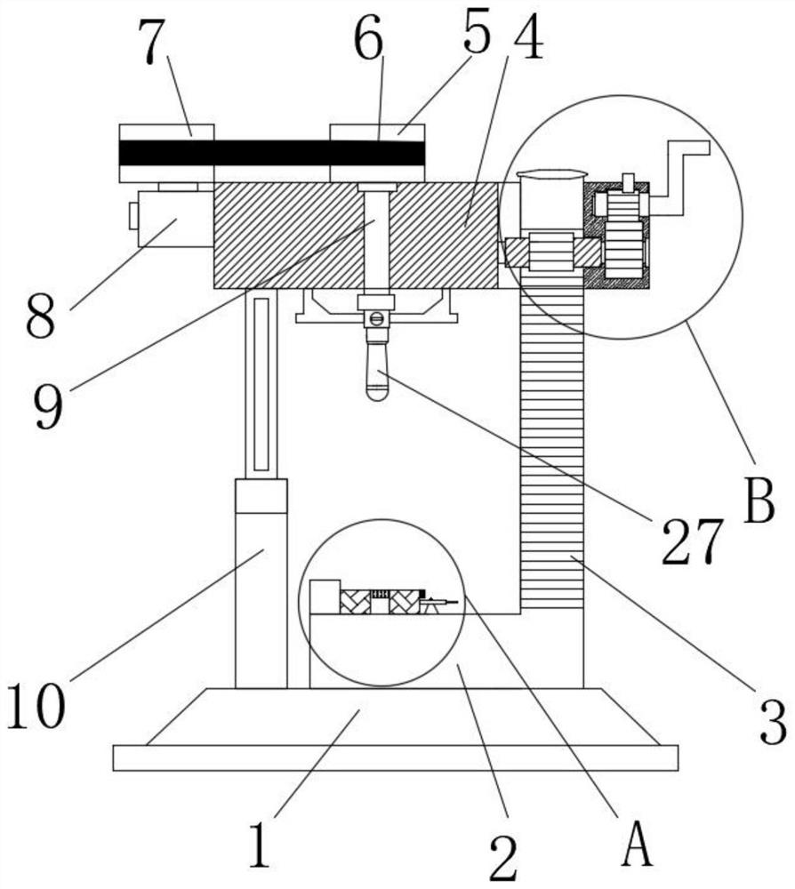
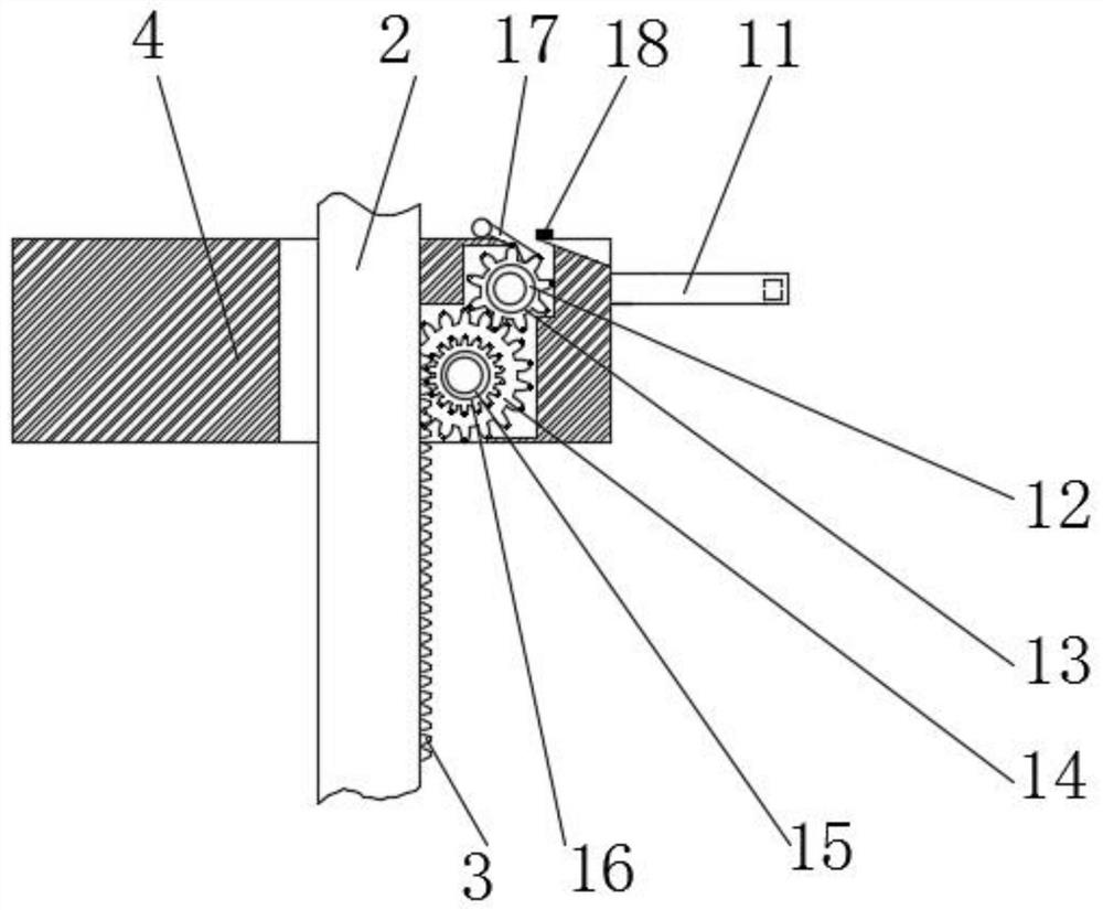
[0026] refer to Figure 1-6 , The drilling equipment used for building construction in this embodiment includes a base 1, a support base 2 is fixedly installed on the top of the base 1, a rack 3 is fixedly installed on one side of the support base 2, and a top plate 4 is arranged above the base 1, The top of the support seat 2 runs through the top plate 4 and is slidably connected with the bottom of the top plate 4. A driving motor 8 is fixedly installed on one side of the top plate 4, and a second pulley 7 is fixedly installed on the output shaft of the driving motor 8. The top of the top plate 4 is rotatably connected with a The first pulley 5, the second pulley 7 and the outer side of the first pulley 5 are covered with the same belt 6, the bottom of the first pulley 5 is fixedly equipped with a drill seat 9, and the bottom of the drill seat 9 runs through the top plate 4 and extends to the top plate 4, the bottom of the drill seat 9 is detachably and fixedly equipped with ...

Embodiment 2

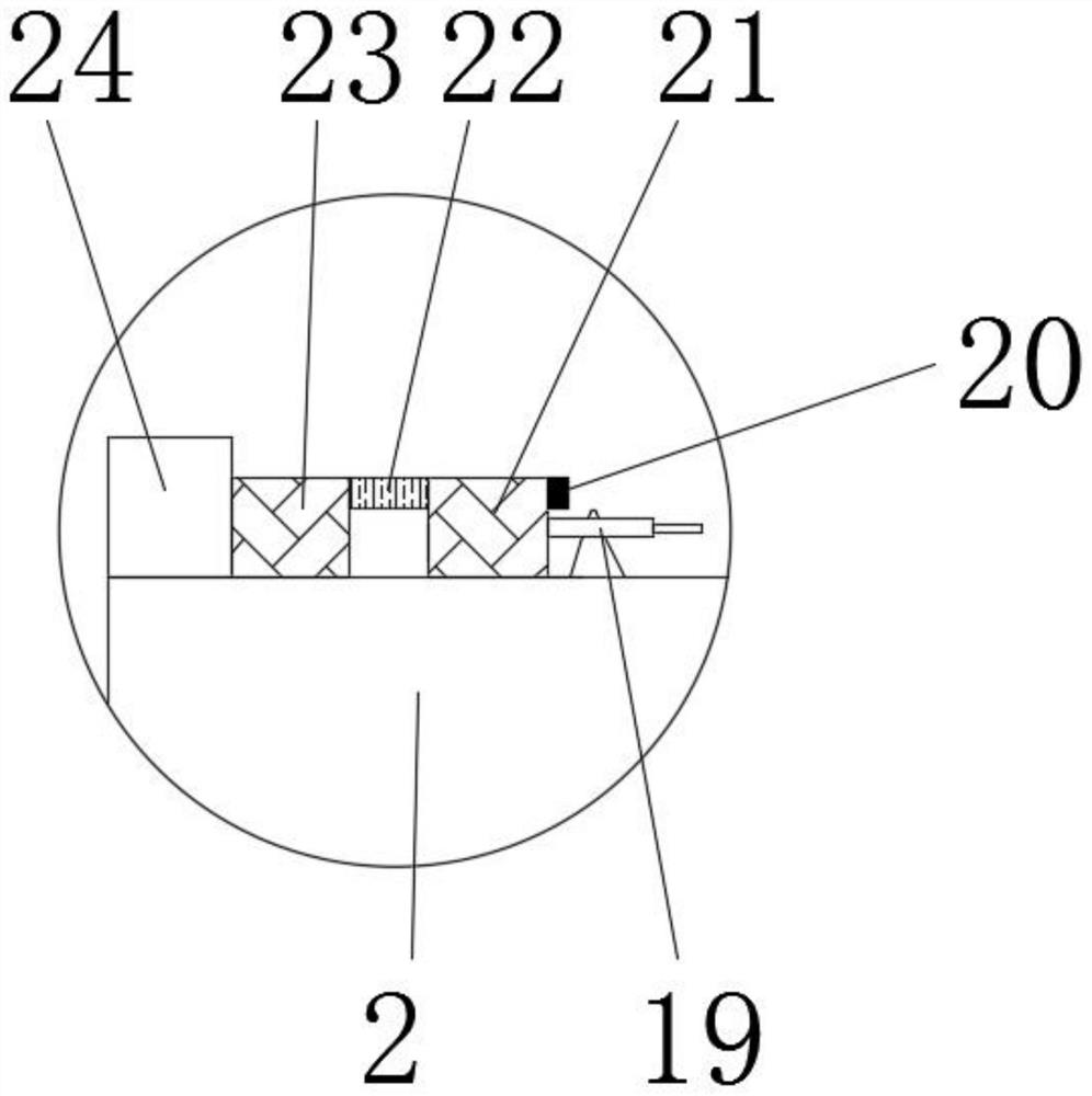
[0028]Improvement is made on the basis of Embodiment 1; the fixing assembly includes a fixing plate 24 fixedly installed on the top of the support base 2, a second clamping block 23 is fixedly installed on one side of the fixing plate 24, and a second clamping block 23 is fixedly installed on one side of the second clamping block 23. The first bolt 22 and the second bolt 25, the top of the support seat 2 is rotatably equipped with an eccentric wheel 19, the top of the support seat 2 is slidably installed with a first clamping block 21, and one side of the first bolt 22 and the second bolt 25 all penetrates The first clamping block 21, the outer thread of the first bolt 22 is connected with the first nut 20, the outer thread of the second bolt 25 is connected with the second nut 26, the top of the base 1 is fixedly installed with the telescopic rod 10, the telescopic rod 10 The top of the top and the bottom of the top plate 4 are fixedly connected, and the one-way brake assembly...


PUM


Abstract

The invention belongs to the field of construction punching, and particularly relates to drilling equipment for building construction. In order to solve the problems that a traditional punching machine cannot freely rise and fall and steel is difficult to fix in the steel punching process, the following scheme is proposed, and the drilling equipment comprises a base; a supporting base is fixedly mounted on the top of the base; a rack is fixedly mounted on one side of the supporting base, and a top plate is arranged above the base; the top of the supporting base penetrates through the top plate, and is slidably connected to the bottom of the top plate; and a driving motor is fixedly mounted on one side of the top plate. According to the designed technical scheme, a first gear and a second gear are meshed and a third gear is driven to rotate so that a drill bit seat freely rises and falls, and accordingly holes in any depth can be formed in the steel; a fixing assembly is limited by a first nut and a second nut; the steel cannot be deviated in the high-speed punching process, and the punching efficiency is improved; the operation is convenient, and the structure is simple; and the actual design requirement is better met.

Description

technical field [0001] The invention relates to the field of construction drilling, in particular to a drilling device for building construction. Background technique [0002] The process of steel drilling is often involved in the process of building construction. Although most of the traditional drilling equipment is mechanical arms, although labor-saving, they cannot freely adjust the lifting of the drill seat during the drilling process, resulting in the inability to determine the depth of the hole. Moreover, the hardness of the steel is high and the density may be uneven, so it is difficult to form a compact structure and it is difficult to fix the position. [0003] The purpose of this new model is to overcome the problems that the traditional punching machine cannot move up and down freely and the steel is difficult to fix in the process of punching steel. A drilling device for building construction is proposed to solve the above-mentioned problems. Contents of the ...

Claims


Application Information

Patent Timeline
IPC IPC(8): B23B39/00B23B47/18B23B47/06B23B49/00B23Q3/06
CPCB23B39/00B23B49/00B23Q3/06B23Q5/34B23Q5/10
Inventor 唐娟
Owner 唐娟
Learn More