Blow-off valve

A technology for relief valves and bonnets, applied in the direction of lift valves, valve details, valve devices, etc., can solve the problems of small pollution, long bonnet travel, unsuitable relief valve structure, etc., to achieve small strokes, reasonable transmission structure, and guaranteed The effect of long-term stable operation

Pending Publication Date: 2021-10-26
QINHUANGDAO QINYE HEAVY IND
View PDF0 Cites 0 Cited by
  • Summary
  • Abstract
  • Description
  • Claims
  • Application Information

AI Technical Summary

Problems solved by technology

[0002] Stability of gas pressure in furnaces and pipelines is the key to the normal operation of metallurgical, chemical, energy and other systems, and relief valves, as key equipment for stabilizing gas pressure in furnaces and pipelines, are widely used in metallurgical, chemical, energy and other systems; As a cutting-edge technology in the iron and steel industry, smelting reduction ironmaking has the advantages of short process, less investment, and less pollution. However, the temperature of the gas generated by it (1450°C) is much higher than that of blast furnace ironmaking. The existing relief valve structure is no longer suitable. suitable for this situation
The existing relief valve has a long bonnet stroke and a slow release speed, and the high-temperature medium will wash the valve when the valve is released, which may easily cause the valve to not be tightly sealed and affect the use effect of the relief valve

Method used


Image

  • Blow-off valve
  • Blow-off valve
  • Blow-off valve

Examples


Embodiment Construction

[0038] In order to make the purpose, technical solutions and advantages of the embodiments of the present invention more clear, the technical solutions of the embodiments of the present invention will be clearly and completely described below in conjunction with the drawings of the embodiments of the present invention.

[0039] Unless otherwise defined, the technical terms or scientific terms used in the present invention shall have the usual meanings understood by those skilled in the art to which the present invention belongs. "First", "second" and similar words used in the present invention do not indicate any order, quantity or importance, but are only used to distinguish different components. "Comprising" or "comprising" and similar words mean that the elements or items appearing before the word include the elements or items listed after the word and their equivalents, without excluding other elements or items. Words such as "connected" or "connected" are not limited to p...


PUM


Abstract

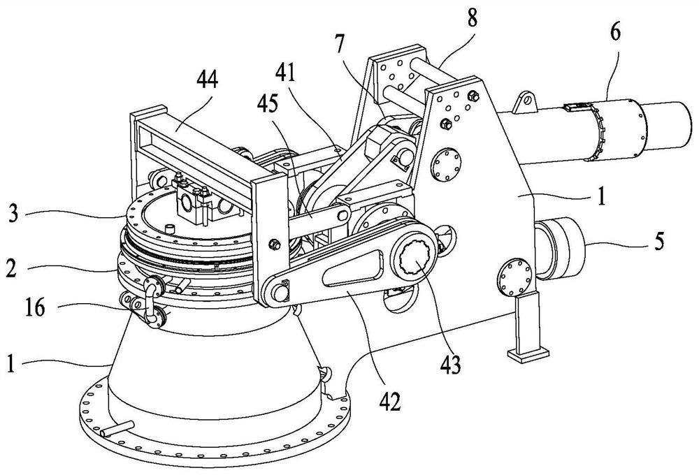
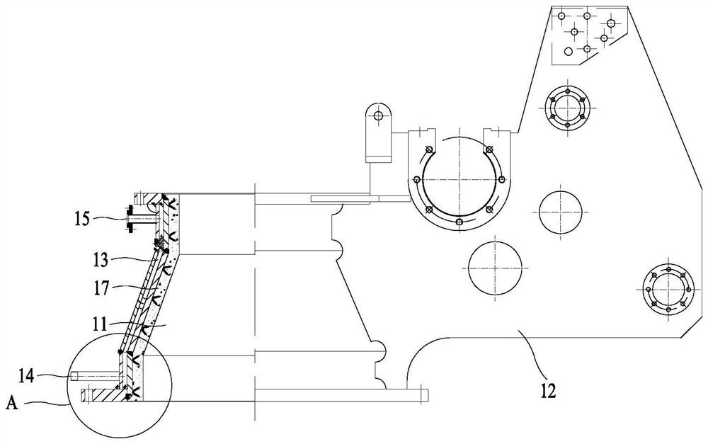
The invention relates to a blow-off valve. The blow-off valve comprises a valve body; a valve seat mounted on the valve body; a valve deck mounted at the top of the valve seat and used for sealing a top opening of the valve seat; a transmission mechanism which comprises a crank, a rocker and a transmission main shaft, wherein the transmission main shaft is rotationally arranged on the valve body, the bent position of the crank and one end of the rocker are rotationally connected to the transmission main shaft, and the other end of the rocker is hinged to the valve deck; a driving mechanism mounted on the valve body and connected with one end of the crank, wherein the driving mechanism can drive the crank to rotate and drive the rocker to rotate through the crank, so that the valve deck is driven to move to open or close a second valve cavity; and a disc spring barrel rotatably installed on the valve body through a connecting rod and hinged to the other end of the crank, wherein when the driving mechanism drives the crank to rotate, the disc spring barrel can be driven to rotate, and pressure is applied to the valve deck so that the valve deck can be sealed on the valve seat. The blow-off valve is resistant to high temperature, the stroke of the valve deck is small, automatic and rapid blow-off can be achieved, and long-time stable operation can be guaranteed.

Description

technical field [0001] The invention relates to the technical field of valves, in particular to a relief valve. Background technique [0002] Stability of gas pressure in furnaces and pipelines is the key to the normal operation of metallurgical, chemical, energy and other systems, and relief valves, as key equipment for stabilizing gas pressure in furnaces and pipelines, are widely used in metallurgical, chemical, energy and other systems; As a cutting-edge technology in the iron and steel industry, smelting reduction ironmaking has the advantages of short process, less investment, and less pollution. However, the temperature of the gas generated by it (1450°C) is much higher than that of blast furnace ironmaking. The existing relief valve structure is no longer suitable. applicable to this condition. The existing relief valve has a long valve cover stroke and a slow release speed, and the high-temperature medium will wash the valve when the valve is released, which may ea...

Claims


Application Information

Patent Timeline
Patent Type & Authority Applications(China)
IPC IPC(8): F16K1/20F16K1/32F16K1/36F16K1/42F16K27/02F16K31/122F16K31/46F16K31/52F16K49/00
CPCF16K1/2007F16K1/2014F16K1/2057F16K1/205F16K1/2035F16K1/32F16K1/36F16K1/42F16K27/0227F16K31/122F16K31/46F16K31/521F16K49/005
Inventor 袁军王锋顷永宏刘远庆刘杰高红亮王亚明孙世杰张晶边志华才坤张寿彪刘颖于昆
Owner QINHUANGDAO QINYE HEAVY IND
Why Eureka
Try Eureka