A spacer design method for rod end ball joint
A design method and spacer technology, which is applied in the field of shock absorption of elastic rubber parts, can solve the problems of affecting anti-fatigue performance, high product cost, and very high precision requirements, and achieve the effects of good molding, long life, and simplified operation process
- Summary
- Abstract
- Description
- Claims
- Application Information
AI Technical Summary
Problems solved by technology
Method used
Image
Examples
Embodiment 1
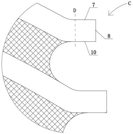
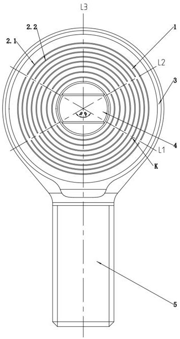
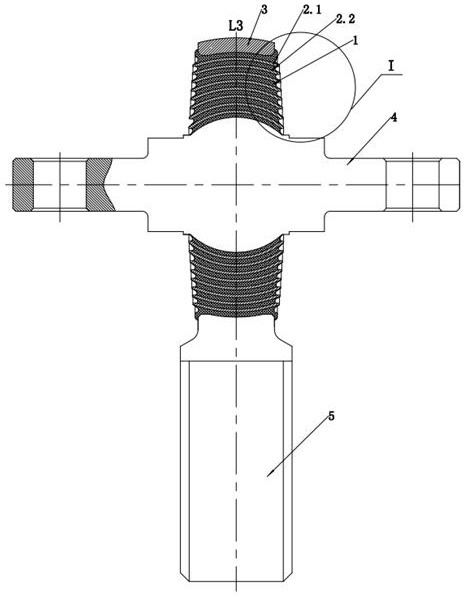
[0040] This example is attached Figure 2-6 As shown, a spacer design method for a rod end ball hinge, the above-mentioned rod end ball hinge includes an outer sleeve 3, a mandrel 4, a rubber layer 1 and a rod portion 5, and the rubber layer 1 is located between the outer sleeve 3 and the mandrel 4, and the outer sleeve There is a rod part 5 on the top, and the rod part 5 is a threaded handle. like image 3 As shown, a multi-layer spacer is arranged in the rubber layer 1, and the multi-layer spacer divides the rubber layer 1 into a multi-layer structure; such as figure 2 and Figure 5 As shown, the upper side 2.6 of the spacer, the lower side 2.7 of the spacer and the end face 2.5 of the spacer are arranged on the spacer, and one end of the end face 2.5 of the spacer is connected to the upper side 2.6 of the spacer, and the end face 2.5 of the spacer is opposite to the spacer The other end of the side 2.6 is connected with the lower side 2.7 of the spacer, the upper side 2.6...
Embodiment 2
[0052] This example is attached Figure 7-9 As shown, the difference between the second embodiment and the first embodiment is that the spacer is 9 layers, that is, the rubber layer 1 is divided into 10 layers; In the inclined setting, a tip B1 is formed at the intersection of the upper side 2.6 of the spacer and the end face 2.5 of the spacer, and the tip B1 is used to make point contact with the mold to position the spacer axially during the vulcanization process; the inclined spacer end face 2.5 and The intersection point B1 of the upper side surface 2.6 of the spacer is positioned in point contact with the mold 9 .
PUM
 Abstract
Description
Claims
Application Information
 - R&D Engineer
- R&D Manager
- IP Professional
- Industry Leading Data Capabilities
- Powerful AI technology
- Patent DNA Extraction
Browse by: Latest US Patents, China's latest patents, Technical Efficacy Thesaurus, Application Domain, Technology Topic, Popular Technical Reports.
© 2024 PatSnap. All rights reserved.Legal|Privacy policy|Modern Slavery Act Transparency Statement|Sitemap|About US| Contact US: help@patsnap.com


