
Universal multi-model oil separation barrel integration device for screw compressor

A technology of screw compressors and integrated devices, which is applied to the components of pumping devices for elastic fluids, mechanical equipment, machines/engines, etc., which can solve the problems of pipeline installation and after-sales service, cooler blockage, cooling effect, leakage Oil or improper configuration and other problems to achieve the effect of solving low operating efficiency, avoiding fuel injection efficiency, extending efficiency and life

Pending Publication Date: 2021-10-26
王伯全
View PDF4 Cites 0 Cited by
  • Summary
  • Abstract
  • Description
  • Claims
  • Application Information

AI Technical Summary

Problems solved by technology

[0004] At present, the existing screw compressors on the market are separated from the oil filter and the oil filter. The oil filter is usually installed on the pipeline, which increases the troubles in pipeline installation and after-sales service, such as: oil leakage or improper configuration. cause oil problems
Specifically, the oil filter cannot directly filter out impurities and particulate matter, causing impurities and particulate matter to directly reach the cooler, which may easily lead to blockage of the cooler or poor cooling effect, which in turn will indirectly cause the oil injection efficiency of the head of the screw compressor and the overall The operating efficiency of the screw compressor

Method used


Image

  • Universal multi-model oil separation barrel integration device for screw compressor

Examples


Embodiment Construction

[0018] In order to make the purpose, technical solutions and advantages of the embodiments of the present invention clearer, the technical solutions in the embodiments of the present invention will be clearly and completely described below in conjunction with the drawings in the embodiments of the present invention. Obviously, the described embodiments It is a part of embodiments of the present invention, but not all embodiments. Based on the embodiments of the present invention, all other embodiments obtained by persons of ordinary skill in the art without making creative efforts belong to the protection scope of the present invention.

[0019] In the description of the present invention, it should be understood that the terms "one side", "the other side", "both sides", "between", "middle", "upper end", "lower end" etc. indicate orientation or The positional relationship is based on the orientation or positional relationship shown in the drawings, which is only for the conven...


PUM


Abstract

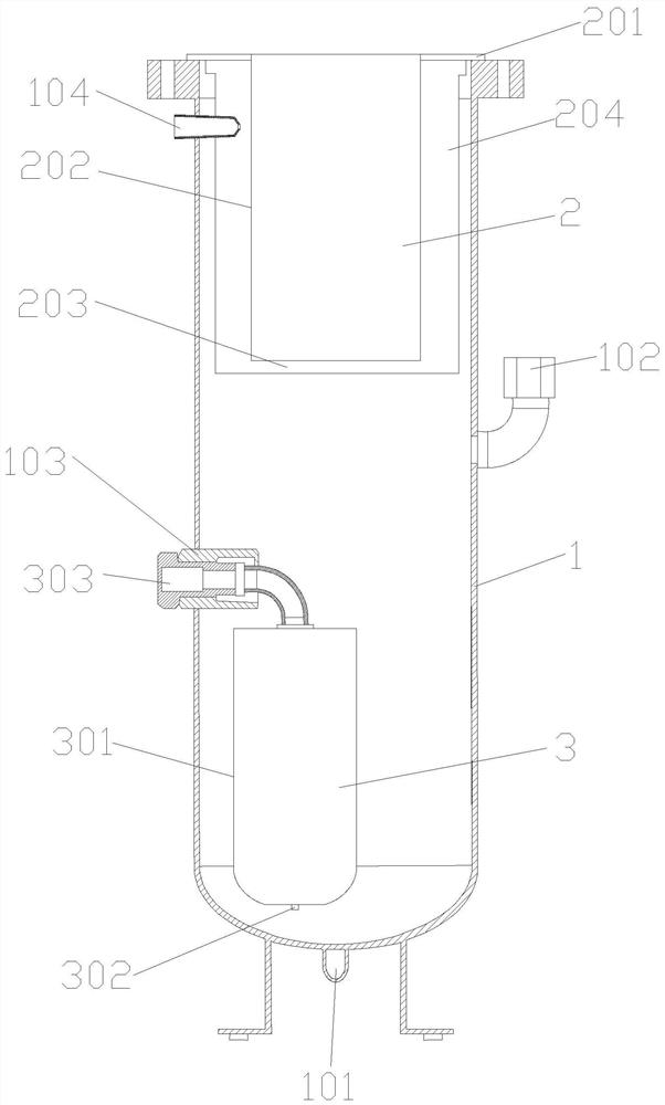
The invention discloses a universal multi-model oil separation barrel integration device for a screw compressor. The universal multi-model oil separation barrel integration device is provided with an oil-gas separation barrel, an oil-gas separator and an engine oil filter are arranged in the oil-gas separation barrel, a compressed oil-gas inlet is formed in the upper end of the side wall of a barrel body of the oil-gas separation barrel, a compressed air outlet is formed in a barrel cover of the oil-gas separation barrel, and an oil drainage hole is formed in the lower end of the barrel body of the oil-gas separation barrel; the oil-gas separator comprises a fixed flange, a first-stage oil crude separation barrel at the lower end of the fixed flange and a second-stage oil separation net at the bottom of the first-stage oil crude separation barrel; a centrifugal channel is formed between the first-stage oil crude separation barrel and the inner wall of a barrel body of the oil-gas separation barrel for separation, and then separation is performed again through a third extremely fine separation core; and the engine oil filter comprises a filter body, an engine oil inlet at the lower end of the filter body, an engine oil filter screen in an inner cavity of the filter body and a clean engine oil outlet at the upper end of the filter body. The engine oil filter of the device directly filters out impurities and particulate matters at the foremost end, and then the engine oil directly enters the cooler to be cooled, and then enters the machine head of the compressor.

Description

technical field [0001] The invention relates to the technical field of screw compressors, in particular to a general-purpose multi-model oil separator barrel integration device for screw compressors. Background technique [0002] In the screw compressor, while compressing the gas, a large amount of oil is injected into the interdental volume of the compressor, and the oil-air mixture formed by the oil and the compressed gas is discharged to the oil-gas of the unit after undergoing the same compression process. In the separator, the oil and gas are separated in the oil-gas separator, and the separated air is discharged into the user pipe network, and the separated oil re-enters the compressor after cooling to form an oil cycle, and a small amount of lubrication that cannot be separated The oil is exhausted with the air, and the oil-air separator is one of the main equipment in the screw compressor unit system. In order to reduce the oil content in the exhaust of the unit and ...

Claims


Application Information

Patent Timeline
IPC IPC(8): F04C29/02F04C29/04F04C18/16
CPCF04C29/026F04C29/04F04C18/16F04C18/082
Inventor 王伯全
Owner 王伯全
Learn More