A steel plate type stirrup with ring belt in the beam-column node area of ​​a rigid structure and its construction method

A beam-column joint and stirrup technology is applied in the field of ring-belt steel plate stirrups in the beam-column joint area of ​​a stiff structure and its construction field, which can solve the problems of insufficient construction quality, prolonged construction period, inconvenient construction, etc., and achieve accurate and convenient installation. , The effect of improving construction quality and improving convenience

Active Publication Date: 2022-04-15
南京明辉建设有限公司
View PDF9 Cites 1 Cited by
  • Summary
  • Abstract
  • Description
  • Claims
  • Application Information

AI Technical Summary

Problems solved by technology

[0004] However, the stirrup connection in the above-mentioned node area requires a large number of high-altitude steel bar welding, and high-altitude operation and welding construction between cylindrical steel bars are very inconvenient. The success rate of the conventional one-time acceptance is about 80%, which has great impact on construction. The quality and the convenience of construction all have a great impact, which makes the construction period longer, etc.
[0005] To sum up, the stirrup connection in the joint area of ​​the existing rigid structure has the defects of inconvenient construction and insufficient construction quality

Method used


Image

  • A steel plate type stirrup with ring belt in the beam-column node area of ​​a rigid structure and its construction method
  • A steel plate type stirrup with ring belt in the beam-column node area of ​​a rigid structure and its construction method
  • A steel plate type stirrup with ring belt in the beam-column node area of ​​a rigid structure and its construction method

Examples


Embodiment 1

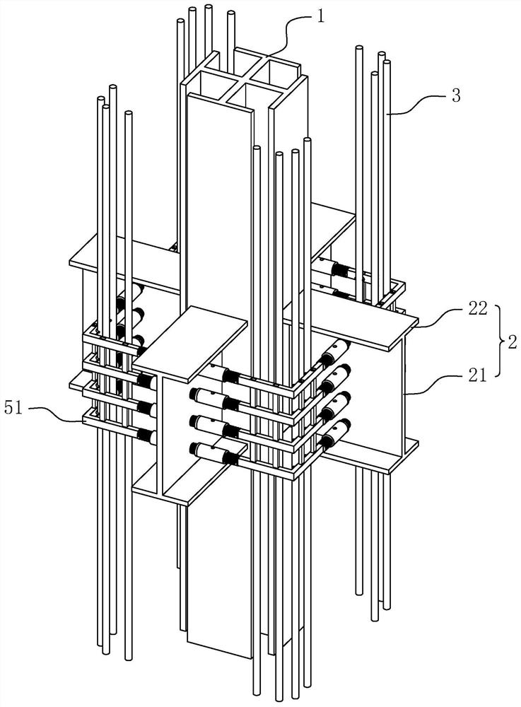
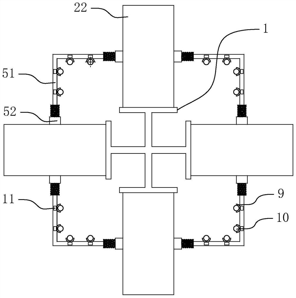
[0041] refer to figure 1 , which is a steel plate type stirrup in the joint area of ​​the beam-column of a rigid structure disclosed in the embodiment of the present application. This kind of ring-band steel plate type stirrup comprises vertically arranged shaped steel column 1, the cross section of shaped steel column 1 is cross-shaped, and beams 2 are horizontally welded on the four vertical sides of shaped steel column 1. Vertically be provided with some longitudinal main ribs 3 around. The beam 2 includes a web 21 arranged vertically to the steel column and a wing 22 fixedly connected to the top and bottom of the web 21 in parallel. The two largest surfaces of the web 21 are vertically arranged, and the web 21 and the wing 22 are close to the steel column 1 One end of each is welded on the steel column 1.

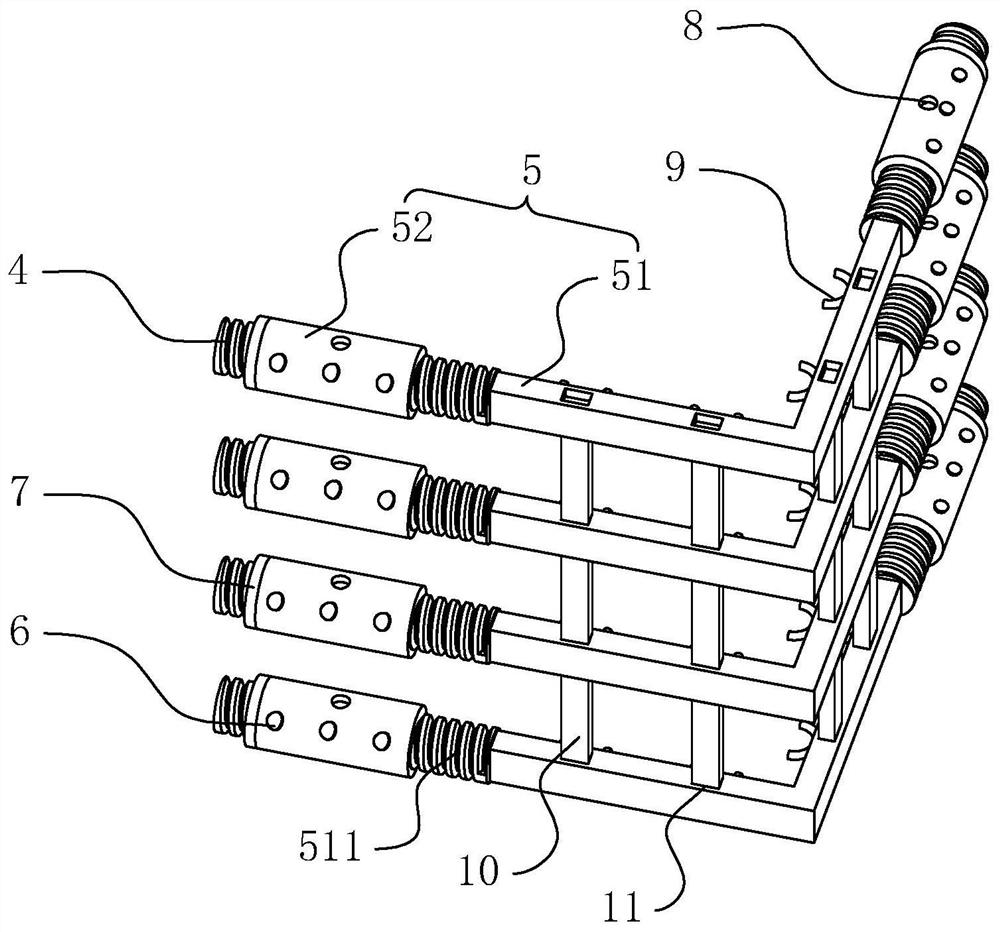
[0042] refer to figure 1 and figure 2 , both sides of the vertical direction of each web 21 are horizontally provided with threaded columns 4, the threaded columns...

Embodiment 2

[0047] A construction method for a ring-band steel plate type stirrup in a beam-column joint area of ​​a stiff structure, based on the above-mentioned structure of a ring-band steel plate type stirrup in a beam-column joint area of ​​a stiff structure, comprising the following construction steps:

[0048] Step 1: First install the threaded column on the beam 2 in the factory area, which can be welded or integrally formed;

[0049] Step 2: Use arc welding to first weld the beam 2 on the steel column 1 on the ground, and weld the supporting structure on the steel column 1 to prevent the deformation of the connecting rib 51 when the stirrup structure 5 is installed later. The supporting structure can be For the support plate, it is only necessary that the side of the support plate away from the shaped steel column 1 can abut against the connecting rib plate 51;

[0050] Step 3: Install the stirrup structure 5, specifically: install the stirrup structure 5 from bottom to top, firs...


PUM


Abstract

The present application relates to a steel plate type stirrup with ring belt in the joint area of ​​a rigid structure beam and column and its construction method. Threaded columns are arranged horizontally on the board, and a stirrup structure is provided between the threaded columns on two adjacent beams. The stirrup structure includes L-shaped connecting ribs, threaded ends arranged at both ends of the connecting ribs, and threaded connections. The threaded sleeves on the threaded ends, the two threaded sleeves are respectively and simultaneously threaded on the threaded columns of the two beams. In this application, threaded sleeve connection is used instead of steel bar welding, which makes the welding process easier, improves construction convenience, and the threaded sleeve structure is more stable and strong, improving construction quality.

Description

technical field [0001] The present application relates to the field of building construction, in particular to a ring-band steel plate stirrup in the beam-column node area of ​​a rigid structure and a construction method thereof. Background technique [0002] Stiff structure (also known as shaped steel concrete or reinforced concrete), consisting of concrete, shaped steel columns, beams, longitudinal reinforcement and stirrups. To put it simply, section steel is added to the original reinforced concrete structure. After adding section steel, the bearing capacity of components can be effectively improved. Stiff structures are widely used in high-rise and super high-rise building construction projects. [0003] During the construction process, due to the stricter structural strength requirements of the joints between the steel columns and the beams, the stirrups in the joint area of ​​the beams and columns need to be densely arranged, but the installation of the stirrups becom...

Claims


Application Information

Patent Timeline
Patent Type & Authority Patents(China)
IPC IPC(8): E04B1/24E04B1/58E04C5/03E04G21/14E04G21/12E04G21/18
CPCE04B1/24E04B1/58E04B1/5812E04C5/03E04G21/14E04G21/123E04G21/1841E04B2001/2454E04B2001/2466E04B2001/2406E04B1/2403
Inventor 杨树国邓斌周林斌蒋照发刘铃
Owner 南京明辉建设有限公司
Why Eureka
Try Eureka