Step-by-step dry deacidification system and method for blast furnace gas

A technology of blast furnace gas and dry method, which is applied in separation methods, chemical instruments and methods, gas dust removal, etc., and can solve problems such as gas leakage, corrosion of auxiliary equipment, and hidden dangers of normal smelting safety in blast furnaces.

Active Publication Date: 2021-10-26
SHANGHAI UNIV
View PDF5 Cites 1 Cited by
  • Summary
  • Abstract
  • Description
  • Claims
  • Application Information

AI Technical Summary

Problems solved by technology

However, the blast furnace gas after dry dedusting will cause severe corrosion of gas pipelines, residual pressure turbine generator (TRT) blades and other ancillary equipment, which will cause vibration of TRT blades, gas leakage and heat storage efficiency reduction of hot blast stove checker bricks etc., which seriously affect the normal operation of the residual pressure and waste heat recovery device and the normal smelting of the blast furnace and bring about major safety hazards

Method used


Image

  • Step-by-step dry deacidification system and method for blast furnace gas
  • Step-by-step dry deacidification system and method for blast furnace gas

Examples


Embodiment Construction

[0021] The following describes several preferred embodiments of the present invention with reference to the accompanying drawings, so as to make the technical content clearer and easier to understand. The present invention can be embodied in many different forms of embodiments, and the protection scope of the present invention is not limited to the embodiments mentioned herein.

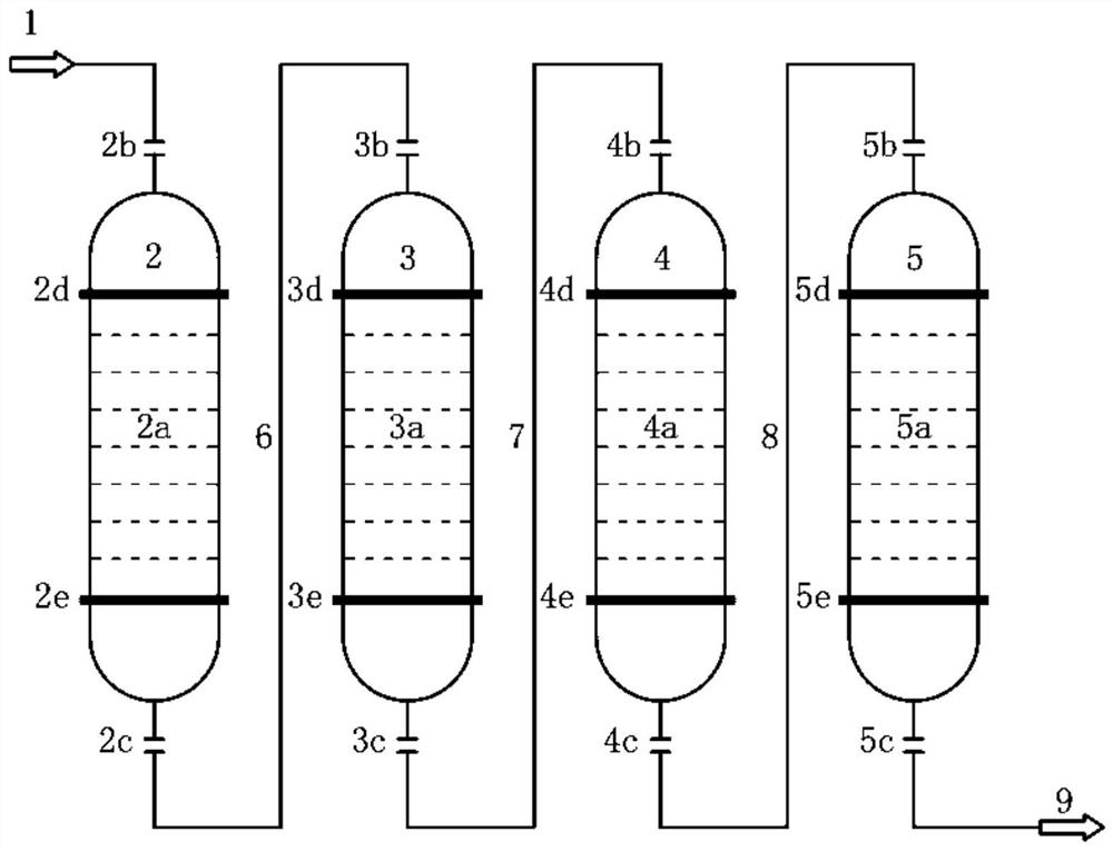
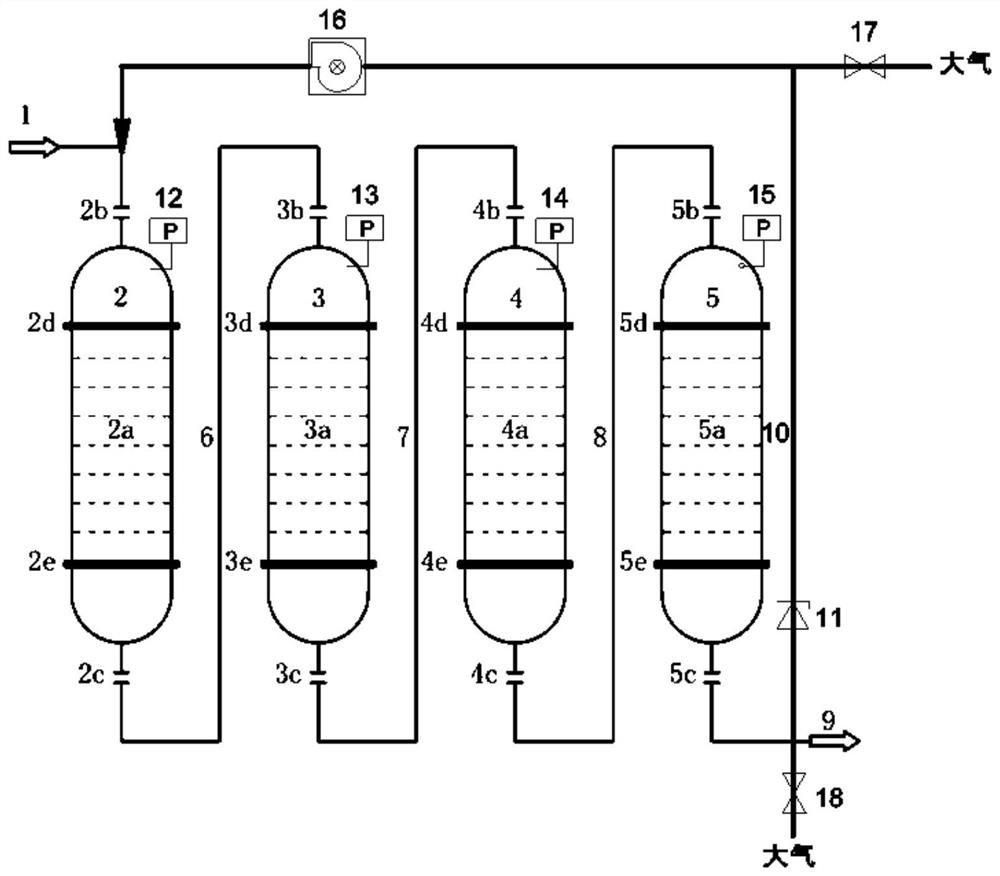
[0022] see figure 1 , the step-by-step dry deacidification system of blast furnace gas according to the present invention comprises:

[0023] Blast furnace clean gas supply subsystem after dedusting, dehydration drying tower dehydration subsystem, inorganic acid removal tower to remove HCl, H 2 S subsystem, organic sulfur hydrolysis tower hydrolysis COS subsystem, desulfurization tower removal of H 2 S subsystem, deacidification agent replacement subsystem.

[0024] (1) Blast furnace clean gas supply subsystem after dedusting: this subsystem sends the raw gas generated on the top of the blast furna...


PUM


Abstract

The invention discloses a step-by-step dry deacidification method for blast furnace gas, which comprises the following steps: raw gas generated at the top of a blast furnace passes through a gravity dust collector and a bag-type dust collector, then clean gas is fed into a dehydration drying tower through a gas input pipeline for dehydration, a dehydration drying agent bed layer is arranged in the middle of the dehydration drying tower, and anhydrous CaCl2 desiccant is packed in the shell. Coal gas passing through the dehydration drying tower is fed into an inorganic acid removal tower through a pipeline to remove HCl and H2S, an inorganic acid adsorbent bed layer is mounted in the middle of the interior of the inorganic acid removal tower, and the interior of the inorganic acid removal tower is filled with a CaO adsorbent. The coal gas passing through the inorganic acid removal tower is fed into an organic sulfur hydrolysis tower through a pipeline for COS hydrolysis, a hydrolysis catalyst bed layer is mounted in the middle of the interior of the organic sulfur hydrolysis tower, and the interior of the organic sulfur hydrolysis tower is filled with a COS hydrolysis catalyst. The coal gas passing through the organic sulfur hydrolysis tower is fed into a desulfurizing tower through a pipeline to remove H2S, a desulfurizing agent bed layer is mounted in the middle of the interior of the desulfurizing tower, a Fe2O3 desulfurizing agent is packed in the desulfurizing tower, and the coal gas passing through the desulfurizing tower enters a coal gas output pipeline.

Description

technical field [0001] The present invention relates to blast furnace gas purification, and more particularly to a system and method for dry removal of acidic components including sulfur and chlorine in blast furnace gas. Background technique [0002] The dry dedusting process of blast furnace gas and residual pressure and waste heat power generation technology are advanced technologies for the country to promote energy conservation and emission reduction in the iron and steel industry and develop circular economy. Blast furnace gas dry dust removal technology has gradually replaced the traditional wet dust removal technology and has become the first choice for blast furnace gas dust removal technology due to its advantages of water saving, high dust removal efficiency, full use of gas sensible heat, and high power generation capacity of gas residual pressure. Practice has proved that compared with the traditional wet dust removal technology, the dry dust removal technology ...

Claims


Application Information

Patent Timeline
Patent Type & Authority Applications(China)
IPC IPC(8): C10K1/00C10K1/02C10K1/32C10K1/34C10K1/20B01D50/00B01D53/26B01D53/28B01D53/04B01D53/75B01D53/86B01D53/48B01D53/82B01D53/52
CPCC10K1/003C10K1/004C10K1/02C10K1/024C10K1/32C10K1/34C10K1/20B01D53/26B01D53/28B01D53/0407B01D53/75B01D53/8606B01D53/82B01D53/52B01D2253/104B01D2255/808B01D2251/602Y02P20/129
Inventor 张玉文祝凯董辉耿淑华鲁雄刚
Owner SHANGHAI UNIV
Why Eureka
Try Eureka