Automatic unstacker
A depalletizing machine and automatic technology, which is applied in the depalletizing, conveyor, transportation and packaging of objects, can solve the problems of high cost of robot arms, high cost of damage maintenance, and affecting the efficiency of depalletizing, so as to achieve high depalletizing efficiency , low maintenance costs, and improved efficiency
- Summary
- Abstract
- Description
- Claims
- Application Information
AI Technical Summary
Problems solved by technology
Method used
Image
Examples
Embodiment 1
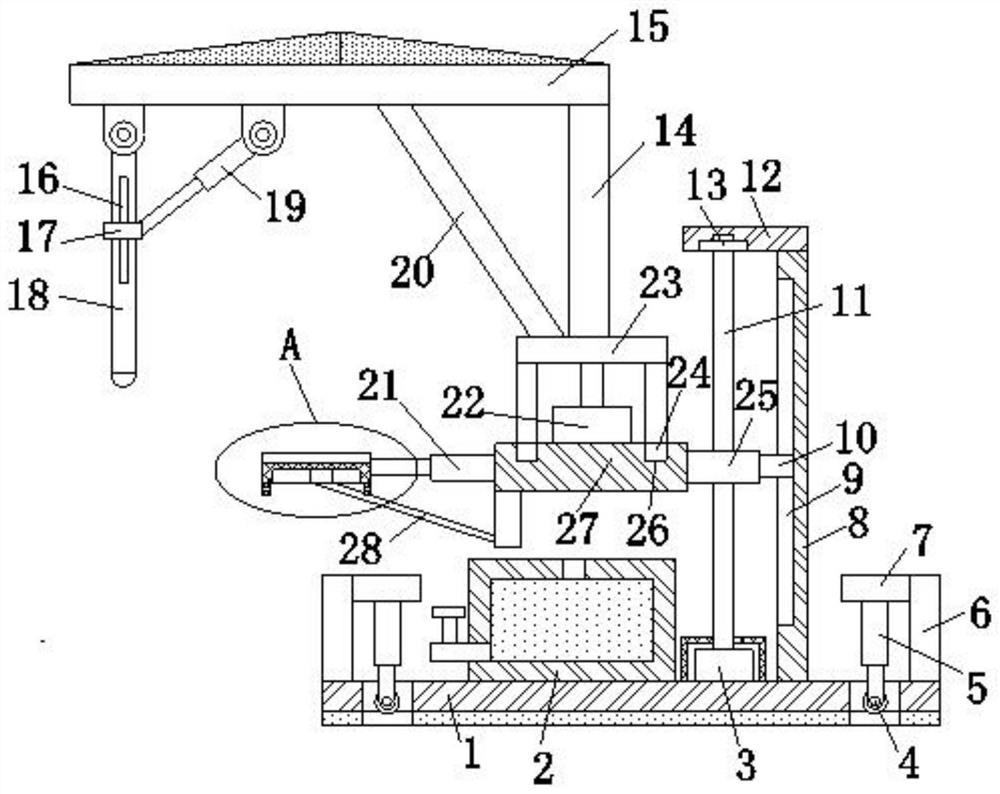
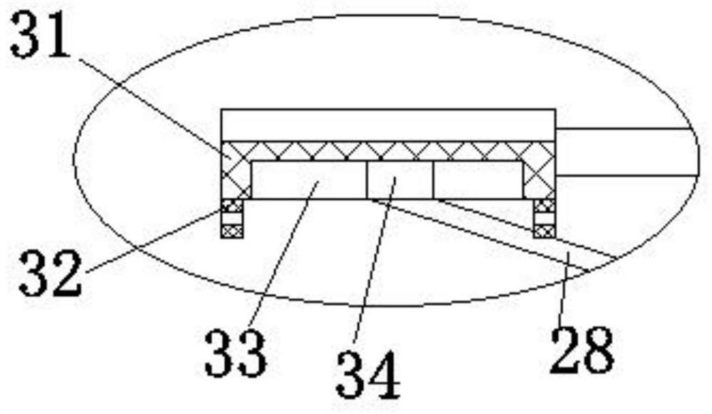
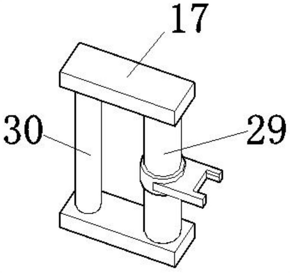
[0026] refer to Figure 1-5 , an automatic destacker, comprising a bottom plate 1, the top of the bottom plate 1 is fixedly connected with a third fixed plate 27 through a jacking mechanism and a rotating motor 22 is installed on the top of the third fixed plate 27, and the output shaft of the rotating motor 22 is connected with The top of the second connecting plate 14 and the second connecting plate 14 is fixedly connected with a top plate 15, and the bottom of the top plate 15 is hinged with an inclination oil cylinder 19 and a toggle plate 18, and the front of the toggle plate 18 is provided with a rectangular opening 16 and inside the rectangular opening 16 Fixed column 30 is provided, the two ends of fixed column 30 are fixed with connection block 17 and are fixed with the connection column 29 that is used for being hinged with the piston rod of inclination oil cylinder 19 between two connection blocks 17, the side of the 3rd fixed plate 27 is provided with The material ...
Embodiment 2
[0028] refer to Figure 1-5, in the case that other parts are the same as in Embodiment 1, the difference between this embodiment and Embodiment 1 is that the jacking mechanism includes a lifting motor 3 installed on the top of the bottom plate 1 and the output shaft of the lifting motor 3 is connected with a screw rod 11 , the top of the base plate 1 is fixed with a mounting plate 8 and the side of the mounting plate 8 is provided with a first sliding groove 9, the screw rod 11 is threaded with an internal thread block 25 and the right side of the internal thread block 25 is fixed with a first sliding groove. Block 10, the first slider 10 is slidably installed in the first chute 9, the third fixed plate 27 is fixed on the left side of the internal thread block 25, the top of the mounting plate 8 is fixedly connected with the first connecting plate 12, the first The bottom of the connecting plate 12 is provided with a bearing 13, the screw rod 11 is provided with the inner rin...
PUM
 Abstract
Description
Claims
Application Information
 - Generate Ideas
- Intellectual Property
- Life Sciences
- Materials
- Tech Scout
- Unparalleled Data Quality
- Higher Quality Content
- 60% Fewer Hallucinations
Browse by: Latest US Patents, China's latest patents, Technical Efficacy Thesaurus, Application Domain, Technology Topic, Popular Technical Reports.
© 2025 PatSnap. All rights reserved.Legal|Privacy policy|Modern Slavery Act Transparency Statement|Sitemap|About US| Contact US: help@patsnap.com


