
Photovoltaic power station energy storage matching system and operation method thereof

A photovoltaic power station and photovoltaic cell technology, applied in the field of physical energy storage, can solve the problems affecting the long-term stability and high-efficiency operation of photovoltaic power stations, the reduction of output power and system life of photovoltaic power stations, the high temperature and efficiency reduction of photovoltaic cells, etc., and achieve low toxicity, Reduce construction and maintenance costs and improve efficiency

Active Publication Date: 2021-10-22
XI AN JIAOTONG UNIV
View PDF10 Cites 0 Cited by
  • Summary
  • Abstract
  • Description
  • Claims
  • Application Information

AI Technical Summary

Problems solved by technology

[0004] In addition, under strong sunshine conditions, the temperature of photovoltaic cells increases, causing the reduction of photovoltaic panel power generation efficiency, resulting in the reduction of output power and system life of photovoltaic power plants
The outdoor working environment where the photovoltaic cells are located will cause dust and foreign matter on the surface of the photovoltaic panels after long-term work, which will further affect the power generation efficiency of photovoltaic cells
The above problems affect the long-term stability and efficient operation of photovoltaic power plants
At present, the dust removal of large-scale photovoltaic power plants mostly adopts quarterly manual dust removal, that is, the surface of photovoltaic cells is washed and cleaned manually with high-pressure water four times a year, which is not only inefficient, but also unable to solve the high temperature and efficiency reduction of photovoltaic cells at noon The problem

Method used


Image

  • Photovoltaic power station energy storage matching system and operation method thereof
  • Photovoltaic power station energy storage matching system and operation method thereof
  • Photovoltaic power station energy storage matching system and operation method thereof

Examples


Embodiment Construction

[0040] Below in conjunction with specific example the present invention is described in further detail:

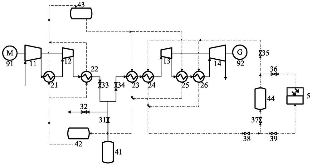
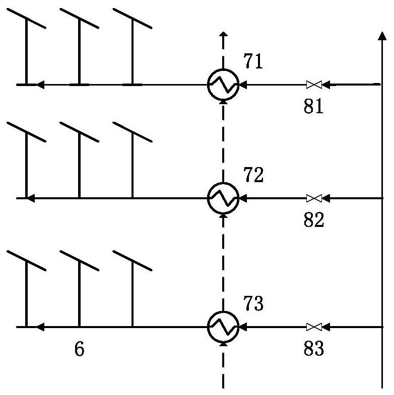
[0041] refer to figure 1 , a photovoltaic power station energy storage supporting system provided by the present invention includes a compressed air energy storage module, a compression heat recovery module, a solar heat supplement module and a photovoltaic cell cooling module; the photovoltaic cell cooling module includes a cooling nozzle 61 arranged above the photovoltaic cell , the cooling nozzle 61 is connected with cooling air or clean water; the compressed air energy storage module includes an energy storage section and an energy release section, and the outlet of the energy storage section and the inlet of the energy release section are connected to the inlet of the high-pressure gas storage chamber 41 through a control valve;

[0042] The energy storage section is equipped with two-stage compressors, the outlets of the compressors are equipped with coolers, the ene...


PUM


Abstract

The invention provides a photovoltaic power station energy storage matching system and an operation method thereof. The system comprises an energy storage section, an energy release section, a solar heat compensation module and a cooling nozzle arranged above a photovoltaic cell. A working medium outlet of the energy storage section is connected with an inlet of the high-pressure gas storage chamber; the working medium outlet of the energy storage section and an outlet of the high-pressure gas storage chamber are connected with a working medium inlet of the energy release section; the energy storage section is provided with two-stage compressors, coolers are arranged at outlets of the compressors, the energy release section is provided with two-stage expansion machines, and preheating heaters and heat supplementing heaters are arranged at inlets of the two-stage expansion machines. A hot medium outlet of the cooler is communicated with the high-temperature water storage tank, a cold medium outlet of the cooler is communicated with the low-temperature water storage tank, the high-temperature water storage tank is connected with the preheating heater, and a heating medium outlet of the preheating heater is communicated with the low-temperature water storage tank; a working medium inlet / outlet of the solar heat compensation module is communicated with a heating medium inlet / outlet of the heat compensation heater; the efficiency of the energy storage system can be obviously improved; solar heat compensation is cleaner, and carbon emission can be effectively reduced.

Description

technical field [0001] The invention relates to the field of physical energy storage, in particular to a photovoltaic power station energy storage supporting system and an operating method thereof. Background technique [0002] Optical resources fluctuate greatly in a short period of time, and the power grid also needs to be dispatched according to user-side loads, which leads to the demand for energy storage in photovoltaic power plants. At present, the policy of new energy supporting energy storage in many provinces is constantly increasing, requiring new energy power stations to be equipped with energy storage systems with 5% to 20% of the rated power generation before grid-connected power generation. Although the energy storage on the grid side has lower overall construction cost and capacity than that on the power generation side, it is more difficult to control and manage the power grid, so the energy storage on the power generation side is irreplaceable. [0003] At ...

Claims


Application Information

Patent Timeline
Patent Type & Authority Applications(China)
IPC IPC(8): H02S10/20H02S40/10H02S40/42H02S40/44H02J15/00
CPCH02S10/20H02S40/425H02S40/44H02S40/10H02J15/006Y02E70/30Y02E10/50Y02E10/60Y02E60/16
Inventor 王焕然葛刚强贺新陶飞跃
Owner XI AN JIAOTONG UNIV
Learn More