A Shaft Generator with Automatic Switching of Auxiliary Excitation

A shaft generator, auxiliary excitation technology, applied in the direction of electromechanical devices, electrical components, electric components, etc., can solve the problems of poor heat dissipation, burn out the user's load, poor cooling effect, etc., to improve the cooling effect and facilitate recycling Effect

Active Publication Date: 2022-06-28
KUNGFU SCI TECH CO LTD
View PDF0 Cites 0 Cited by
  • Summary
  • Abstract
  • Description
  • Claims
  • Application Information

AI Technical Summary

Problems solved by technology

However, since the marine shaft generator is driven by the main diesel engine of the ship, as the operating conditions and speed of the main diesel engine change, the speed and frequency of the shaft generator will change accordingly. When other loads need to be a stable three-phase generator with constant frequency and constant voltage In case of alternating current, ordinary shaft generators cannot meet the requirements. In order to solve this problem, variable speed, constant frequency, constant voltage and constant power devices are usually used.
At present, when the shaft generator used in the market changes in the speed of the prime mover, the voltage of the shaft generator is likely to be out of control because the auxiliary winding excitation cannot be automatically switched, causing the voltage regulator to burn out or the generator to burn out, or even burn out the user's load; And the existing motor heat dissipation method usually cools the motor by water cooling or air cooling, but the water cooling method will cause the temperature of the cooling water to rise rapidly after passing through the motor, and the motor needs to run for a long time, so it needs to continuously input cold water , the waste is serious, and the air cooling method has poor cooling effect. When the motor is running at high speed and for a long time, it is easy to burn out the motor due to poor heat dissipation effect. The existing water cooling and air cooling cannot realize circulating heat dissipation

Method used


Image

  • A Shaft Generator with Automatic Switching of Auxiliary Excitation
  • A Shaft Generator with Automatic Switching of Auxiliary Excitation
  • A Shaft Generator with Automatic Switching of Auxiliary Excitation

Examples


Embodiment

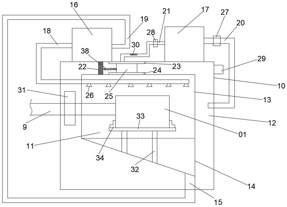
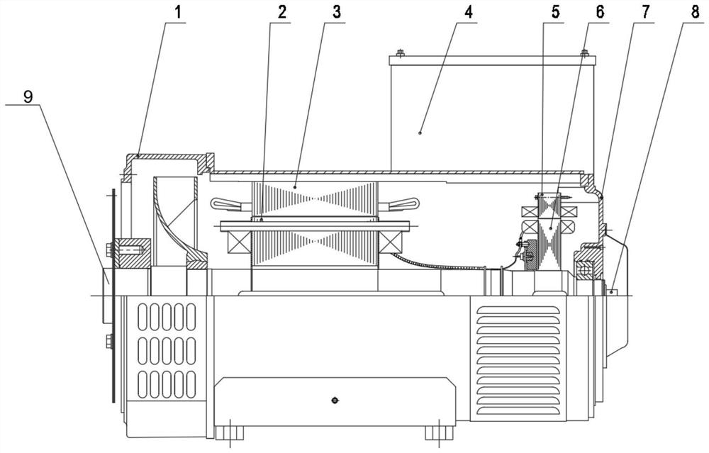
[0028] like Figure 1-Figure 5 As shown, the present invention provides a shaft generator with automatic switching of auxiliary excitation,

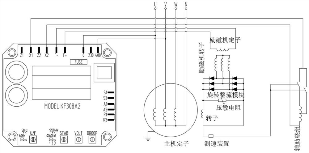
[0029] It includes a shaft generator body 01 and a casing, the shaft generator body 01 is arranged in the casing, and the shaft generator body 01 includes a front end cover 1, a rotor 2, a stator 3, a box 4, an excitation Machine stator 5, exciter rotor 6, rear end cover 7, speed measuring device 8, rotating shaft 9, generator voltage regulator, the speed measuring device 8 is used to detect the rotation speed of the rotating shaft 9, the stator includes stator windings, auxiliary an excitation winding, a switch is electrically connected to the auxiliary excitation winding, and a speed measuring device 8 is electrically connected between the switch and the rotor;

[0030]The casing includes a first casing and a second casing 10. A liquid cooling cavity 11 is formed between the inner side wall of the first casing and the outer side wall ...


PUM


Abstract

The invention discloses a shaft generator with automatic switching auxiliary excitation, which comprises a shaft generator body and a casing, the shaft generator body is arranged in the casing, and the shaft generator body includes a front end cover , rotor, stator, box, exciter stator, exciter rotor, rear end cover, speed measuring device, rotating shaft, generator voltage regulator, the speed measuring device is used to detect the rotating speed of the rotating shaft, and the stator includes a stator winding . Auxiliary excitation winding, where a switch is electrically connected to the auxiliary excitation winding, and a speed measuring device is electrically connected between the switch and the rotor. The invention automatically switches the auxiliary excitation winding through the rotation speed of the shaft generator body collected by the rotary encoder installed on the shaft generator body to ensure that the shaft generator body can work normally at different speeds.

Description

technical field [0001] The invention relates to a generator, in particular to a shaft generator with automatic switching of auxiliary excitation. Background technique [0002] Most of the main diesel engines of ships run under partial loads, and when they operate under low loads below 75% to 85% of the rated power, their economy will decline. If the shaft generator is used, the main engine can be used for a long time. It operates under higher load, so it has good economy. After the main diesel engine is equipped with a shaft generator, it can run under a higher load for a long time, and the efficiency is improved. However, since the marine shaft generator is driven by the main diesel engine of the ship, the speed and frequency of the shaft generator change with the change of the main diesel engine operating conditions and speed. When other loads need to be stable three-phase with constant frequency and constant voltage In the case of alternating current, ordinary shaft gen...

Claims


Application Information

Patent Timeline
Patent Type & Authority Patents(China)
IPC IPC(8): H02K7/20H02K11/21H02K9/20H02K5/20H02K5/04H02K9/10H02K11/25
CPCH02K7/20H02K11/21H02K9/20H02K5/20H02K5/04H02K9/10H02K11/25
Inventor 胡海鹏徐志强聂义勇杨杰
Owner KUNGFU SCI TECH CO LTD
Why Eureka
Try Eureka