
Tracking return control method, automatic walking equipment and readable storage medium

A technology of automatic walking equipment and return control, applied in the direction of non-electric variable control, control/regulation system, two-dimensional position/channel control, etc., which can solve the problems of easily crushed grassland, large distance between signal heads, and large ground damage. , to achieve the effect of guaranteeing the operation effect

Active Publication Date: 2021-10-22
NANJING SUMEC INTELLIGENT TECH CO LTD
View PDF7 Cites 0 Cited by
  • Summary
  • Abstract
  • Description
  • Claims
  • Application Information

AI Technical Summary

Problems solved by technology

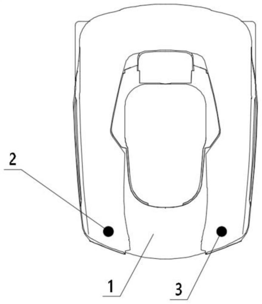
In this process, since the two signal heads of the existing automatic walking equipment are respectively located on the left and right sides of the fuselage, and the distance between the two signal heads is relatively large, the existing automatic walking equipment detects the deflection of the running direction through its two signal heads When , only serious course deflection can be recognized, and there will be more obvious head wobble in the process of tracking along the boundary line
[0004] In addition, under the existing tracking method, when the automatic walking equipment is controlled to return to the base station along the boundary line, since the path is the same each time, the wheel tracks of each run overlap a lot, and it is easy to form bushes near the boundary line due to repeated rolling of the walking wheels. The deeper wheel track will cause greater damage to the ground, and it is easy to crush the grass near the boundary line

Method used

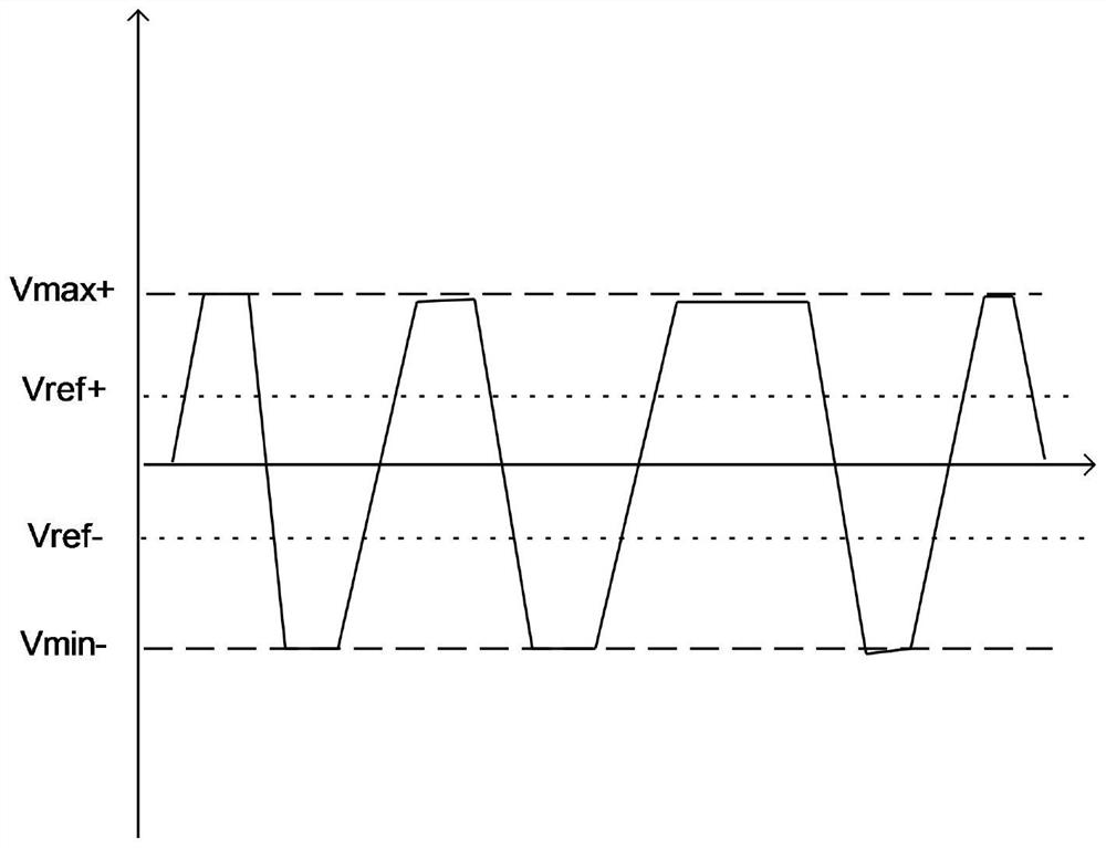
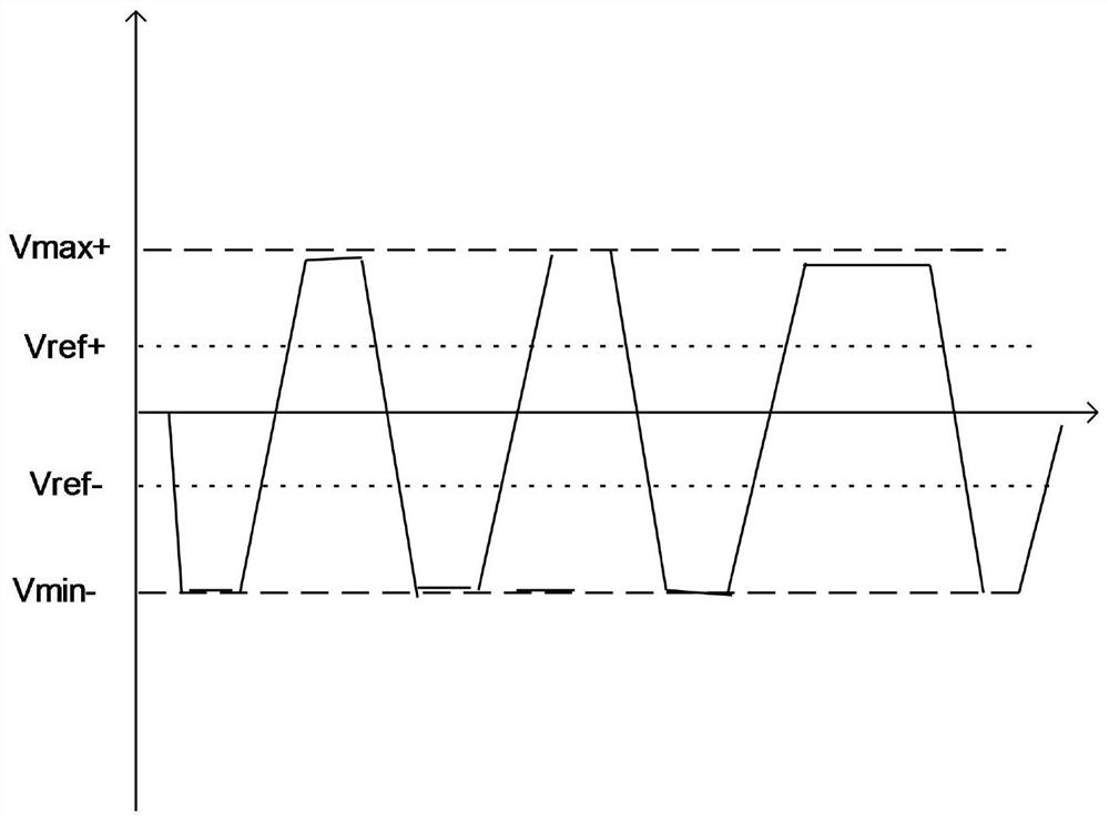

Image

  • Tracking return control method, automatic walking equipment and readable storage medium
  • Tracking return control method, automatic walking equipment and readable storage medium
  • Tracking return control method, automatic walking equipment and readable storage medium

Examples


Embodiment Construction

[0028] In order to make the purpose and technical solutions of the embodiments of the present application clearer, the following will clearly and completely describe the technical solutions of the embodiments of the present application with reference to the drawings of the embodiments of the present application. Apparently, the described embodiments are some of the embodiments of the present application, but not all of them. Based on the described embodiments of the present application, all other embodiments obtained by persons of ordinary skill in the art without creative efforts shall fall within the protection scope of the present application.

[0029] Those skilled in the art can understand that, unless otherwise defined, all terms (including technical terms and scientific terms) used herein have the same meaning as commonly understood by those of ordinary skill in the art to which this application belongs. It should also be understood that terms such as those defined in c...


PUM


Abstract

The invention provides a tracking return control method, automatic walking equipment and a readable storage medium. In the process that the automatic walking equipment returns to the base station along the boundary line, signal detectors at different positions on the automatic walking equipment are selected as main detectors, and the main detectors are kept to alternately swing between the inner side and the outer side of the boundary line in a reciprocating mode along with operation of the automatic walking equipment. As the position of the main detector relative to the body of the automatic walking equipment is the same in the process of returning to the base station each time, the position relation of the bottom operation device of the automatic walking equipment relative to the ground and the boundary line can be adjusted in the reciprocating tracking operation process along the two sides of the boundary line, therefore, the walking path of the automatic walking equipment returning to the base station is adjusted, and the driving wheels of the automatic walking equipment are prevented from repeatedly rolling the grassland in the same path, so that the operation effect of the edge of the working area is guaranteed or the boundary line is protected from being touched by the operation unit.

Description

technical field [0001] The present application relates to the field of automatic walking equipment, and specifically relates to a tracking return control method, automatic walking equipment and a readable storage medium. Background technique [0002] At present, automatic walking equipment such as mowing robots need to use figure 1 The two signal heads shown are respectively installed on both sides of the device to detect the position information of the robot. The existing automatic walking equipment collects the boundary line signals through the signal heads on both sides of the fuselage at the same time, and by separately identifying the signals collected by the two signal heads, it is ensured that the two signal heads are respectively located on the boundary line during the movement of the automatic walking equipment. The inner and outer sides, thereby ensuring that the automatic walking equipment can walk along the boundary line. [0003] When using the above tracking ...

Claims


Application Information

Patent Timeline
Patent Type & Authority Applications(China)
IPC IPC(8): G05D1/02A01D34/00
CPCG05D1/0214A01D34/008G05D1/0219
Inventor 刘贯营成孟哲周国扬刘楷
Owner NANJING SUMEC INTELLIGENT TECH CO LTD
Learn More