Water beating impeller device and mobile air conditioner
A technology of water impeller and impeller, which is applied in air conditioning system, prevention of condensate water, space heating and ventilation, etc., can solve the problems of using more materials and less water, and achieve less material, increase the amount of water, and increase the cooling effect. Effect
- Summary
- Abstract
- Description
- Claims
- Application Information
AI Technical Summary
Problems solved by technology
Method used
Image
Examples
Embodiment 1
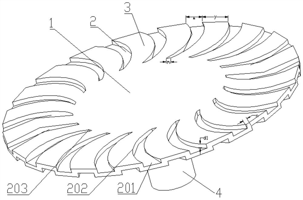
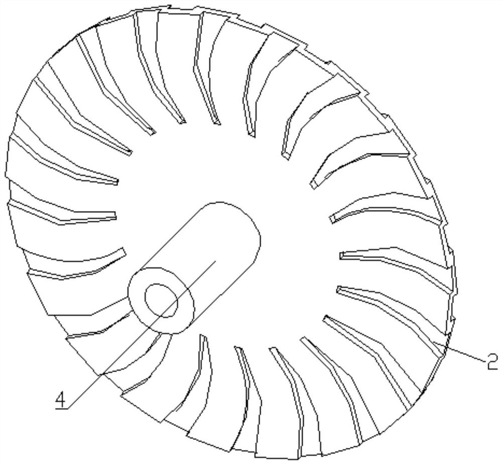
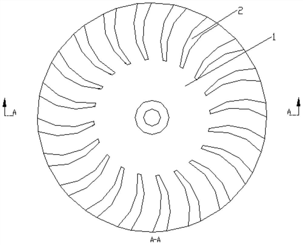
[0036] See attached figure 1 with attached Figure 5 , a water pumping impeller device, comprising a water pumping wheel 1, the water pumping wheel 1 is opened with a flow channel 2 formed by a downwardly recessed groove.
[0037] The way of digging grooves is used as the flow channel 2, which increases the width and depth of the flow channel 2, improves the amount of water pumped by the water pumping impeller 1, and uses less materials, saves costs, and the water pumping wheel 1 is more versatile. The design and manufacturing process is easy to achieve standardization, the effect of the water pumping impeller 1 can be brought into full play, the amount of water pumped is greatly increased compared with before, the cooling effect is increased, and the unit power is reduced.
Embodiment 2
[0039] On the basis of embodiment one, further optimize the structure of the water impeller device described in embodiment one:
[0040] There are multiple flow channels 2, and the multiple flow channels 2 are radially distributed around the center of the impeller.
[0041] Specifically, when the water-feeding impeller 1 is at rest, part of the flow channel 2 extends into the condensed water in the water-feeding tank to fetch water, and the rest of the flow channels 2 are exposed to the air, and the water-feeding impeller 1 is rotating At this time, the flow channel 2 for pumping water is rotated out, and the flow channel 2 for not pumping water is rotated into the condensed water for pumping water, so that a plurality of the flow channels 2 can carry out water pumping in sequence, and the water can be thrown until the condensed water On the device, the amount of water pumped by the water pumping impeller 1 is increased. At the same time, a plurality of the flow channels 2 are...
Embodiment 3
[0049] On the basis of embodiment two, the structure of the water impeller device described in embodiment two is further optimized:
[0050] The flow channel 2 includes a water holding part 202, and the water holding part 202 extends toward the center side of the water pumping impeller 1 to form a blocking end 203 closing the water holding part 202, and the water holding part 202 moves away from the water holding part 202. The center side of the water pumping impeller 1 extends to form a water inlet 201 at the edge of the water pumping wheel 1 .
[0051] The water inlet 201 is an open structure, condensed water enters the flow channel 2 from the water inlet 201, the water holding part 202 holds water, and the blocking end 203 blocks the water to prevent it from entering the The water in the flow channel 2 flows out.
[0052] Preferably, the water holding portion 202 is arc-shaped, gradually widening from the blocking end 203 to the water inlet end 201,
[0053] On the edge s...
PUM
 Abstract
Description
Claims
Application Information
 - Generate Ideas
- Intellectual Property
- Life Sciences
- Materials
- Tech Scout
- Unparalleled Data Quality
- Higher Quality Content
- 60% Fewer Hallucinations
Browse by: Latest US Patents, China's latest patents, Technical Efficacy Thesaurus, Application Domain, Technology Topic, Popular Technical Reports.
© 2025 PatSnap. All rights reserved.Legal|Privacy policy|Modern Slavery Act Transparency Statement|Sitemap|About US| Contact US: help@patsnap.com


