Practical functional adjustable vegetable cutting equipment
A practical and adjustable technology, applied in the direction of metal processing, etc., can solve the problems of waste, time and manpower, and low work efficiency, and achieve the effects of avoiding accidental injury, high safety, and improving work efficiency
- Summary
- Abstract
- Description
- Claims
- Application Information
AI Technical Summary
Problems solved by technology
Method used
Image
Examples
Embodiment 1
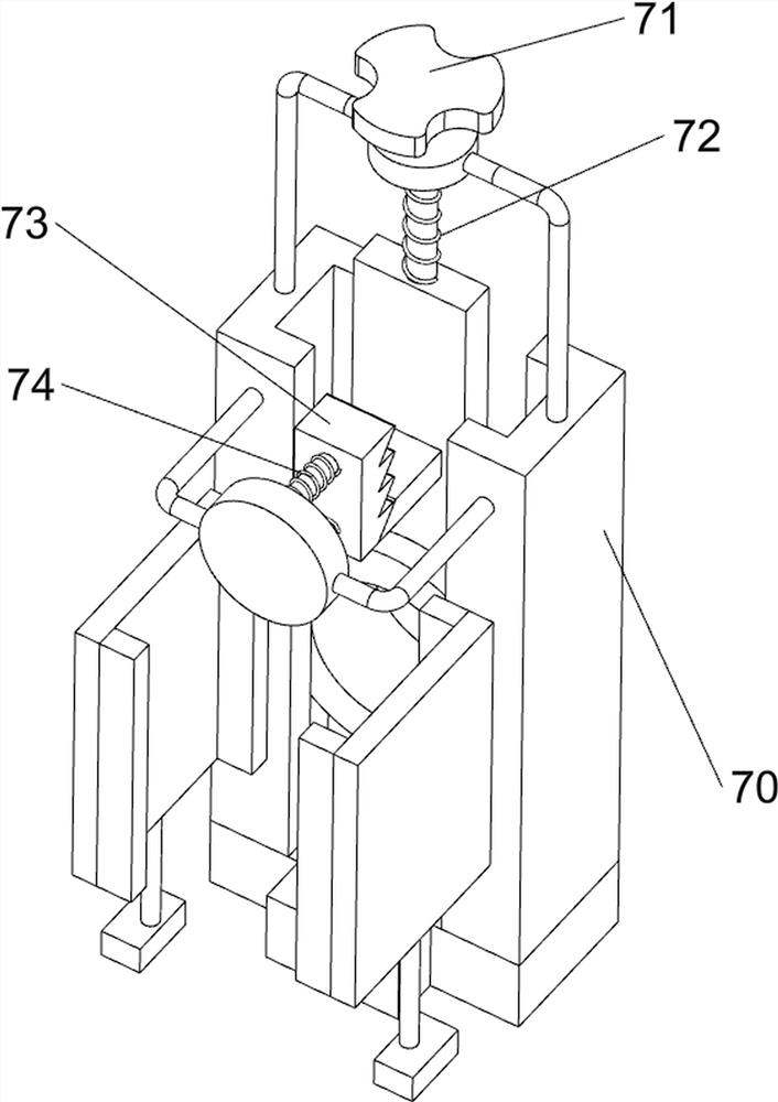
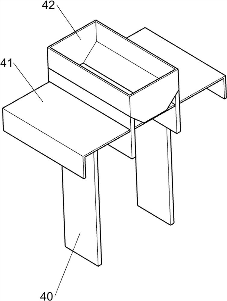
[0069] A practical and functional adjustable vegetable cutting equipment, such as figure 1, figure 2 , image 3 and Figure 4 As shown, it includes a bottom plate 1, a servo motor 2, a push-and-receive mechanism 3, a feeding mechanism 4 and a cutting mechanism 5. A servo motor 2 is provided at the left rear of the top of the bottom plate 1, and the top of the bottom plate 1 is connected to the output shaft of the servo motor 2. There is a propelling and receiving mechanism 3 between them, a blanking mechanism 4 is provided on the left side of the bottom plate 1 top, and a cutting mechanism 5 is provided on the right side of the bottom plate 1 top.
[0070] Propelling and receiving mechanism 3 includes a first support rod 30, a first rotating shaft 31, a second rotating shaft 32, a first pulley assembly 33, a second supporting rod 34, a third rotating shaft 35, a second pulley assembly 36, a Three support rods 37, rolling blocks 38, collection frame 39 and storage box 310, ...
Embodiment 2
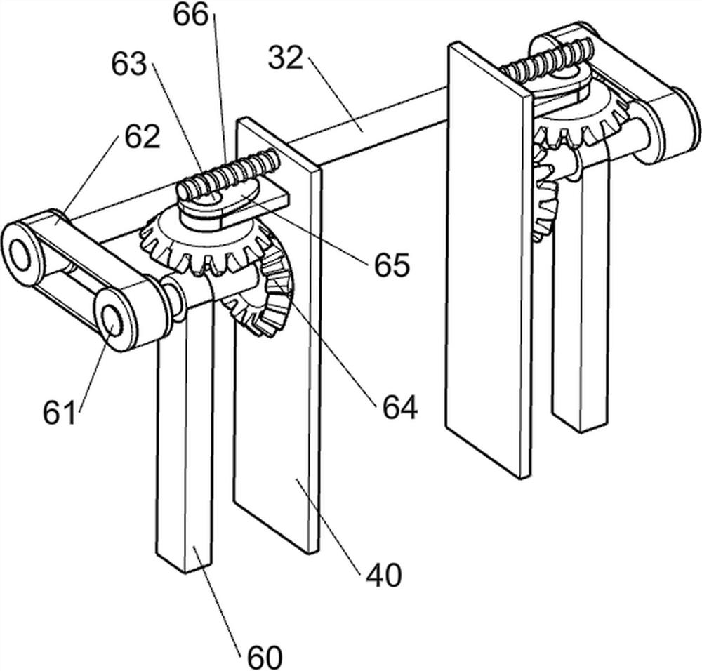
[0075] On the basis of Example 1, such as Figure 5 , Image 6 and Figure 7 As shown, an automatic discharging mechanism 6 is also included, and the automatic discharging mechanism 6 includes a fifth support rod 60, a sixth rotating shaft 61, a fourth pulley assembly 62, a seventh rotating shaft 63, a second bevel gear assembly 64, Cam 65 and the first spring 66, base plate 1 top left side is provided with the 5th support bar 60 symmetrically front and back, the fifth support bar 60 tops are all rotatably provided with the 6th rotating shaft 61, and the 6th rotating shaft 61 outsides are all connected with the second A fourth pulley assembly 62 is arranged between the rotating shafts 32, and a seventh rotating shaft 63 is arranged on the upper part of the bottom frame 40 in front and rear symmetrical rotation. The second bevel gear assembly 64 and the upper part of the seventh rotating shaft 63 are provided with a cam 65 , and the cam 65 cooperates with the pull plate 41 , ...
PUM
 Abstract
Description
Claims
Application Information
 - Generate Ideas
- Intellectual Property
- Life Sciences
- Materials
- Tech Scout
- Unparalleled Data Quality
- Higher Quality Content
- 60% Fewer Hallucinations
Browse by: Latest US Patents, China's latest patents, Technical Efficacy Thesaurus, Application Domain, Technology Topic, Popular Technical Reports.
© 2025 PatSnap. All rights reserved.Legal|Privacy policy|Modern Slavery Act Transparency Statement|Sitemap|About US| Contact US: help@patsnap.com


