
Directly-driven milling device and milling equipment

A milling device, direct-drive technology, applied in the direction of the drive device, milling machine equipment, milling machine equipment details, etc., can solve the problem of poor performance of the drive mode, and achieve the effect of good performance and avoidance of reaction gaps

Active Publication Date: 2021-10-22
思特博恩(常州)新材料科技有限公司 +1
View PDF8 Cites 0 Cited by
  • Summary
  • Abstract
  • Description
  • Claims
  • Application Information

AI Technical Summary

Problems solved by technology

[0003] The main purpose of the present invention is to propose a direct-drive milling device and milling equipment, aiming to solve the problem of poor performance of the drive mode of the current milling device

Method used


Image

  • Directly-driven milling device and milling equipment
  • Directly-driven milling device and milling equipment
  • Directly-driven milling device and milling equipment

Examples


Embodiment Construction

[0038] The following will clearly and completely describe the technical solutions in the embodiments of the present invention with reference to the accompanying drawings in the embodiments of the present invention. Obviously, the described embodiments are only some of the embodiments of the present invention, not all of them. Based on the embodiments of the present invention, all other embodiments obtained by persons of ordinary skill in the art without creative efforts fall within the protection scope of the present invention.

[0039] It should be noted that if there are directional indications involved in the embodiment of the present invention, the directional indications are only used to explain the relative positional relationship, movement conditions, etc. between the components in a specific posture. If the specific posture changes , then the directional indication changes accordingly.

[0040] In addition, if there are descriptions involving "first", "second" and so o...


PUM


Abstract

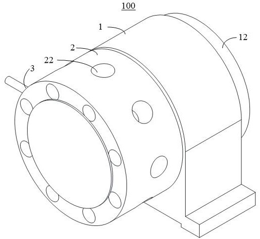
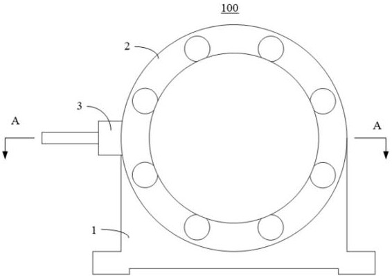
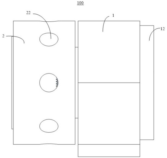
The invention discloses a directly-driven milling device and milling equipment. The milling device comprises a base, a cutter head, a rotary mounting frame and a motor system, wherein the base comprises a first mounting cavity extending in the first direction; the cutter head is rotatably mounted at the front end of the base along the axis in the first direction, a second mounting cavity corresponding to the first mounting cavity is formed in the rear end of the cutter head, and mounting holes penetrating through the second mounting cavity are formed in the peripheral side of the cutter head; the rotary mounting frame is rotatably mounted in the mounting holes along the radial axis of the cutter head, and the rotary mounting frame is used for mounting a milling cutter; and the motor system is in driving connection with the cutter head and the rotary mounting frame, the motor system comprises a first motor directly connected with the cutter head, intermediate links such as a lead screw, a chain and a belt are not needed, the defects of reaction clearance, inertia, friction force and rigidity existing in a traditional scheme are overcome to the maximum extent, and the performance of the scheme is better.

Description

technical field [0001] The invention relates to the technical field of milling, in particular to a direct-drive milling device and milling equipment. Background technique [0002] In the traditional milling device, the driving mode of the cutter head is mostly connected indirectly by the ordinary motor through the transmission mechanism. Although the driving effect can also be achieved, it is inevitable that the traditional driving mode (belts, gears, chains, etc.) , has increased the existence of gaps, elastic deformation, frictional damping and other factors, resulting in reduction and loss of equipment rigidity, response characteristics, and poor performance. Contents of the invention [0003] The main purpose of the present invention is to provide a direct-drive milling device and milling equipment, aiming at solving the problem of poor performance of the driving mode of the current milling device. [0004] In order to achieve the above object, the present invention p...

Claims


Application Information

Patent Timeline
Patent Type & Authority Applications(China)
IPC IPC(8): B23C9/00B23Q1/25B23Q3/00B23Q5/10B23Q17/22B23Q17/24
CPCB23C9/00B23Q1/25B23Q3/00B23Q5/10B23Q17/22B23Q17/2428
Inventor 彭子平苏良飞古金銮
Owner 思特博恩(常州)新材料科技有限公司
Learn More