Eureka AIR delivers breakthrough ideas for toughest innovation challenges, trusted by R&D personnel around the world.

Section steel manufacturing system and method based on BIM and CAM technologies

A technology for manufacturing systems and profiles, applied in the direction of instruments, data processing applications, office automation, etc., can solve the problems of cumbersome tasks, processing preparation time exceeding processing time, and information disconnection, etc., and achieve the effect of reasonable system structure and simple use

Pending Publication Date: 2021-10-19
SHENZHEN MUNICIPAL DESIGN & RES INST +1
View PDF0 Cites 0 Cited by
  • Summary
  • Abstract
  • Description
  • Claims
  • Application Information

AI Technical Summary

Problems solved by technology

[0004] 1. Re-deepen the mold turning (a lot of manual work);
[0005] 2. Statistical engineering quantity (a large amount of labor);
[0012] 2. The purpose of steel structure processing is for welding. The national standards for welding grooves are very complicated, but steel structure processing workers and sample-turning technicians do not know much about welding, and the information is out of touch in the process of transmission.
[0013] 3. In the past, there was no concept of globalization in the process. The better ones were divided into batches and components according to the lifting weight, and the production plan was formulated, resulting in more residual waste in each processing, lower material utilization rate, and more waste.
The repetitive processing path is messy, and the power gas consumption is more wasteful
[0014] 4. The processing trajectory of profiles is very complicated. The mechanical form of processing equipment requires multi-axis linkage. Only robots can do it, but robots are easy to program for batches. For profile processing that is different for each part but requires programming and teaching Generally speaking, the task of path planning is very cumbersome, and the processing preparation time far exceeds the processing time
[0015] Existing equipment can solve the mass production of large quantities and few types, but for more and more personalized designs, it is impossible to provide standardized products

Method used


Image

  • Section steel manufacturing system and method based on BIM and CAM technologies
  • Section steel manufacturing system and method based on BIM and CAM technologies
  • Section steel manufacturing system and method based on BIM and CAM technologies

Examples


Embodiment Construction

[0036] In order to make the technical means, creative features, objectives and effects of the invention easy to understand, the present invention will be further elaborated below in conjunction with specific diagrams.

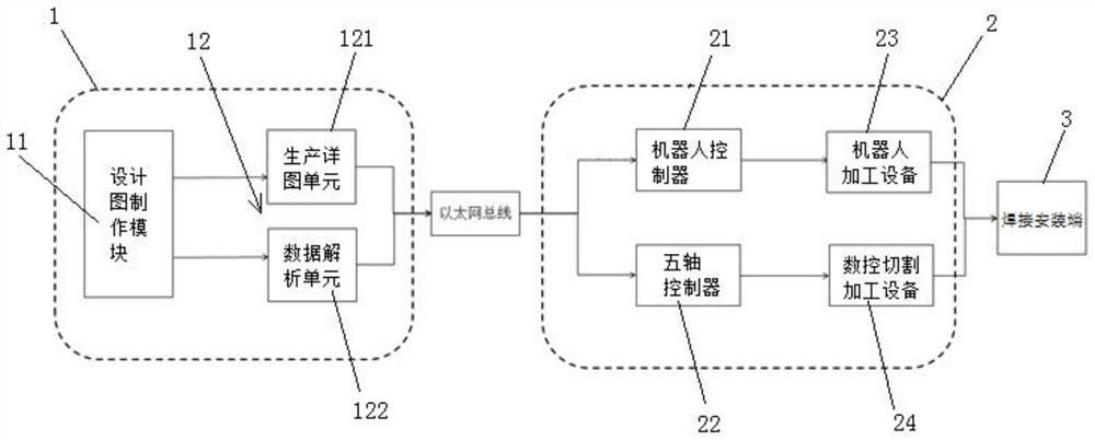
[0037] The first embodiment of the present invention discloses a profile manufacturing system based on BIM+CAM technology, such as figure 2 and image 3 As shown, it includes information transmission between BIM design terminal 1 and CAM production terminal 2. BIM design terminal 1 includes a connected design drawing production module 11 and a profile software processing module 12. CAM production terminal 2 includes interconnected controllers and processing equipment. The profile software processing module 12 is connected to the controller through the Ethernet bus, and the processing equipment is connected to the welding installation end 3 .

[0038] Specifically, the design diagram making module 11 includes TEKLA software, Revit software and Rhino software, ...


PUM


Abstract

The invention discloses a section steel manufacturing system and method based on BIM and CAM technologies. The system comprises information transmission of a BIM design end and a CAM production end, the BIM design end comprises a design drawing manufacturing module and a section steel software processing module which are connected, the CAM production end comprises a controller and a processing device which are connected with each other, the section steel software processing module is connected to the controller through an Ethernet bus, and the processing device is connected to a welding installation end. The system is reasonable in structure and easy to use, the information transmission between the BIM design end and the CAM production end is achieved, informatization transformation is conducted on existing equipment, the existing equipment can accept globally optimized production management arrangement, and only necessary safety maintenance personnel are needed from BIM design to production forming in section steel machining. The information transmission is adopted in the whole process, and the purpose that small-batch and large-type building projects can be produced in an industrialized mode is achieved.

Description

technical field [0001] The invention relates to the technical field of profile processing, in particular to a profile manufacturing system and method based on BIM+CAM technology. Background technique [0002] At present, BIM has entered the key projects of the national science and technology support plan. At present, CAM technology is very mature, and the efficiency in CNC cutting and blanking pipes, profiles, plates, and even steel bars is already very high. The main difficulty restricting the application of BIM at present is how to change from traditional How to automatically provide BIM data to CAM software, and provide it to CNC processing equipment through intelligent nesting has entered the exploration stage in China. Such as figure 1 As shown, currently in China, the design institute provides BIM or CAD models for the processing of profiled steel structures, and the construction unit organizes personnel to turn over the samples and deepen them, and process them into ...

Claims


Application Information

Patent Timeline
IPC IPC(8): G06Q10/10G06F30/20
CPCG06Q10/103
Inventor 王先前雷建王小花吴运欣龙小湖李建璞李跃国
Owner SHENZHEN MUNICIPAL DESIGN & RES INST
Why Eureka
Eureka Blog
Learn More