Optical fiber magnetorefractive effect measurement system and method
A measurement system and magnetotropic technology, which is applied in the use of magneto-optical equipment for magnetic field measurement, the size/direction of the magnetic field, etc., can solve the problems of high system maintenance costs, difficult sensor production, complex sensing structure, etc., and achieve simple structure , to avoid the effect of complex coating process and high sensitivity
- Summary
- Abstract
- Description
- Claims
- Application Information
AI Technical Summary
Problems solved by technology
Method used
Image

Examples
Embodiment 1
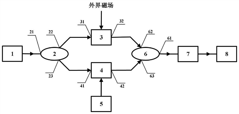
[0042] In this example, see figure 1 , an optical fiber magnetorefractive effect measurement system, including laser 1, coupler A 2, sensing fiber 3, reference fiber 4, carrier generator 5, coupler B 6, photodetector 7, data acquisition and processing module 8;
[0043] The output port of the laser 1 is connected to the first port 21 of the coupler A 2, the second port 22 of the coupler A 2 is connected to the first port 31 of the sensing fiber 3, and the third port 23 of the coupler A 2 Connect with the first port 41 of the reference fiber 4; the second port 32 of the sensing fiber 3 is connected with the second port 62 of the coupler B 6, and the second port 42 of the reference fiber 4 is connected to the second port 62 of the coupler B 6. The three ports 63 are connected; the first port 61 of the coupler B 6 is connected with the input port of the photodetector 7; the input port of the data acquisition and processing module 8 is connected with the output port of the photod...
Embodiment 2
[0049] This embodiment is basically the same as the first embodiment, and the special features are:
[0050] In this example, see figure 1 , coupler A 2, sensing fiber 3, reference fiber 4, coupler B 6 are connected to form a Mach-Zehnder fiber interferometer, sensing fiber 3 constitutes the sensing arm of the Mach-Zehnder fiber interferometer, and reference fiber 4 constitutes a Mach-Zehnder fiber interferometer. - the reference arm of the Zehnder fiber optic interferometer, the first port 21 of the coupler A 2 is the optical input port of the Mach-Zehnder fiber optic interferometer, and the first port 61 of the coupler B 6 is the optical output port of the Mach-Zehnder fiber optic interferometer .
[0051] In this example, see figure 1 , the system is based on the magnetorefractive effect of the sensing fiber 3, the refractive index of the sensing fiber 3 is modulated by the external magnetic field, causing the optical path difference of the two optical signals in the sens...
Embodiment 3
[0055] This embodiment is basically the same as the above-mentioned embodiment, and the special features are:
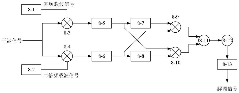
[0056] In this example, see figure 1 and figure 2 , a system and method for measuring the optical fiber magnetorefractive effect according to claim 1, comprising the following steps:
[0057] a. The optical signal output by the laser 1 is divided into two beams of light transmitted by the sensing fiber 3 and the reference fiber 4 through the coupler A 2. The two beams of light interfere at the coupler B 6, and the intensity of the interference light signal is determined by the photodetector 7. detection;
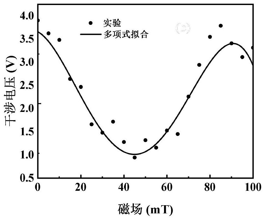
[0058] b. During the DC magnetic field measurement, a DC magnetic field is applied to the sensing fiber 3, and the magnetic field changes the refractive index of the sensing fiber 3, causing the optical path difference of the optical signal in the sensing fiber 3 and the reference fiber 4 to change, changing the coupler B 6 The output interference light signal ...
PUM
 Abstract
Description
Claims
Application Information
 - R&D
- Intellectual Property
- Life Sciences
- Materials
- Tech Scout
- Unparalleled Data Quality
- Higher Quality Content
- 60% Fewer Hallucinations
Browse by: Latest US Patents, China's latest patents, Technical Efficacy Thesaurus, Application Domain, Technology Topic, Popular Technical Reports.
© 2025 PatSnap. All rights reserved.Legal|Privacy policy|Modern Slavery Act Transparency Statement|Sitemap|About US| Contact US: help@patsnap.com