


Quick Research
Generate reliable direction feasibility study reports for your R&D in just a few steps.

Technical Q&A
Discover and master advanced knowledge NOW. Basics, ideas, possibilities, all at once.

Find Solutions
As an expert in R&D theories, this can generate solutions to your technical problems instantly.

Evaluate Feasibility
Analyze your overall solution with one click, know your potential R&D risks in advance.

Monitor Landscape
Get weekly tech updates, stay abreast of the latest tech innovations and key insights.
Three-side turning and fixed advertising picture combined advertising door
A three-sided turning and advertising technology, which is applied in the field of advertising doors, can solve the problems of long time-consuming pasting pictures, trapping, and small cross-sectional size of blades, etc., to reduce the time for pasting pictures, low manufacturing and use costs, simple and reliable mechanical structure Effect
- Summary
- Abstract
- Description
- Claims
- Application Information
AI Technical Summary
Problems solved by technology
Method used
Image

Examples
Embodiment 1
[0039] The advertising barrier with the combination of the three-sided turning of the grooved wheel and the fixed advertising screen
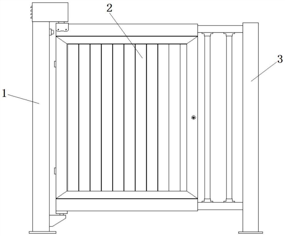
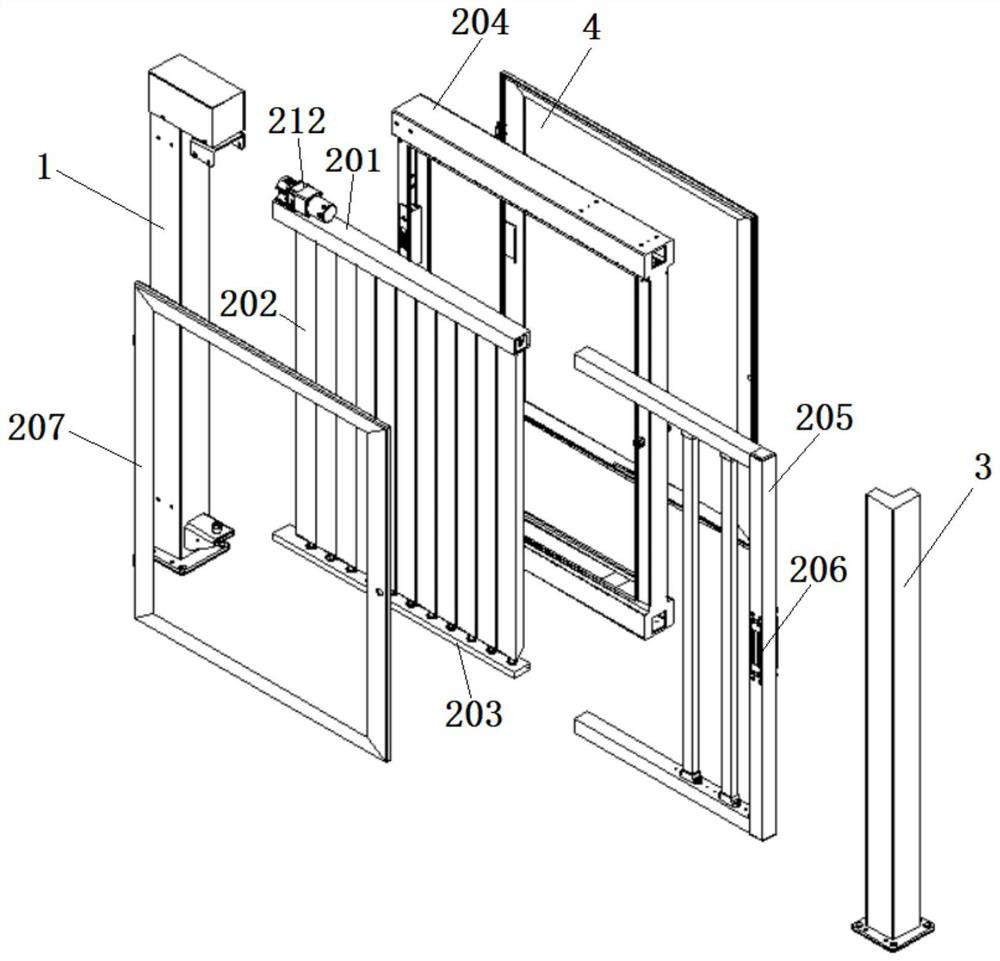
[0040] Such as figure 1 As shown, a kind of advertising door combined with a three-sided turning and fixed advertising screen of the present invention includes a main column assembly 1, a door body mechanism 2 and an auxiliary column assembly 3, and the main column assembly 1 is a power output part, which is connected with the wide door body mechanism 2 connection, so that the door body mechanism 2 can rotate relative to the main column assembly 1 to complete the door opening and closing actions; the auxiliary column assembly 3 acts as a door closing limit, and is attracted to it after the door body mechanism 2 is closed in place to prevent external force from opening the door , A card reader for controlling the electromagnetic lock 206 is arranged on the auxiliary column assembly 3, so as to facilitate the identification of the personnel enter...
Embodiment 2
[0047] Such as Figure 6 As shown, the difference from Embodiment 1 is that a rack-and-pinion drive vane turning mechanism is set in the upper cross bar 201, which includes a power mechanism 212, a driven rack 216, a driving rack 217, a connecting bar 218 and multiple sets of driven gears Component 219; the power mechanism 212 is fixed on the end of the upper cross bar 201, the passive rack 216 is connected with the transmission rack 217 through the connecting bar 218, and the power mechanism 212 can drive the transmission rack 217 to reciprocate left and right by driving the passive rack 216 , multiple groups of driven gear assemblies 219 are arranged in sequence on one side of the transmission rack 217 .
[0048] Such as Figure 7 As shown, the driven gear assembly 219 includes a gear seat 2101, a driven gear 2102, a driven shaft and two bearings. The center of the driven gear 2102 is fixed with a passive shaft, and the lower end of the driven shaft is connected to the uppe...
Embodiment 3
[0051] Such as Figure 8 As shown, the difference from Embodiment 1 is that a bevel gear-driven blade turning mechanism is provided in the upper crossbar 201, which includes a power mechanism 212, a transmission shaft 2105, a driving bevel gear 2106, and a driven bevel gear assembly 2107; the power mechanism 212 is fixed At the end of the upper cross bar 201 and drive the transmission shaft 2105 to rotate, a plurality of driving bevel gears 2106 are respectively arranged on one transmission shaft 2105 .
[0052] Such as Figure 9 As shown, the lower end of the passive bevel gear assembly 2107 is connected to the upper end of the triangular blade unit, and each passive bevel gear assembly 2107 is meshed with a driving bevel gear 2106, which drives the triangular blade unit to rotate 120 degrees each time, thereby achieving forward and backward rotation. The single-row triangular blade assembly 202 is displayed in three sets of advertisement images, and the advertisement image ...
PUM
 Abstract
Description
Claims
Application Information
 - R&D Engineer
- R&D Manager
- IP Professional
- Industry Leading Data Capabilities
- Powerful AI technology
- Patent DNA Extraction
Browse by: Latest US Patents, China's latest patents, Technical Efficacy Thesaurus, Application Domain, Technology Topic, Popular Technical Reports.
© 2024 PatSnap. All rights reserved.Legal|Privacy policy|Modern Slavery Act Transparency Statement|Sitemap|About US| Contact US: help@patsnap.com