Wide-viewing-angle composite polaroid
A polarizer and wide viewing angle technology, applied in the field of polarizers, can solve problems such as uneven transmittance of polarizers, and achieve the effect of reducing brightness changes and uniform transmittance
- Summary
- Abstract
- Description
- Claims
- Application Information
AI Technical Summary
Problems solved by technology
Method used
Image

Examples
Embodiment 1
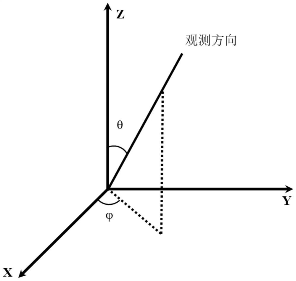
[0036] figure 1 It is a schematic diagram of the reference system for observing the transmittance of the polarizer at different viewing angles, refer to figure 1 , the angle between the line of sight and the Z axis is the polar angle θ, and the angle between the projection of the line of sight on the XY plane and the X axis is the azimuth angle . In the XY plane, the X-axis direction is defined as the 0° direction.
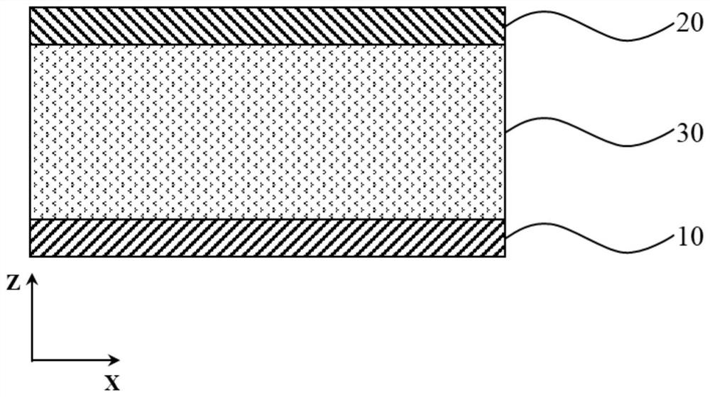
[0037] figure 2 It is a schematic cross-sectional structure diagram of a wide viewing angle composite polarizer proposed by the present invention, which includes a first polarizing layer 10 , an optical active layer 30 and a second polarizing layer 20 in its structure.
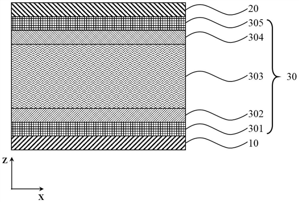
[0038] image 3 It is a schematic cross-sectional structure diagram of a wide viewing angle composite polarizer provided in Example 1 of the present invention, Figure 4 for image 3 Schematic diagram of the cross-sectional structure of the liquid crystal layer, Figure 5 is the direction...
Embodiment 2
[0050] Figure 11 It is a schematic cross-sectional structure diagram of a wide viewing angle composite polarizer provided in Example 2 of the present invention, Figure 12 for Figure 11 The structural formulas of the three monomers that make up the optically active layer of the liquid crystal polymer, refer to Figure 11 with Figure 12 The composite wide viewing angle polarizer includes a first polarizing layer 10, a liquid crystal optically active layer 40 and a second polarizing layer 20, wherein the first polarizing layer 10 and the second polarizing layer 20 are iodine-based polarizers, and the liquid crystal optically active layer 40 is made of HCM- 021, a liquid crystal polymer composed of three monomers, HCM-020 and HCM-009 (monomers were purchased from Jiangsu Hecheng Display Technology Co., Ltd.). The liquid crystal optical active layer 40 includes a lower substrate 401 and a liquid crystal polymer layer 402, wherein the thickness of the lower substrate 401 is 1...
Embodiment 3
[0054] Figure 14 A schematic cross-sectional structure diagram of a wide viewing angle composite polarizer provided in Example 3 of the present invention, the composite wide viewing angle polarizer includes a first polarizing layer 10, a combined wave plate optical rotation layer 50 and a second polarizing layer 20, wherein the first polarizing layer 10. The second polarizing layer 20 is an iodine-based polarizer, the combined wave plate optically active layer 50 is a multi-layer combined wave plate, and the wave plate is an R138 polymer wave plate (purchased from Sanlipu Optoelectronics Technology Co., Ltd.). The combined wave plate optical active layer includes a first wave plate 501, a second wave plate 502, a third wave plate 503, a fourth wave plate 504, a fifth wave plate 505, a sixth wave plate 506, and a seventh wave plate of the same material and thickness. wave plate 507 , eighth wave plate 508 and ninth wave plate 509 . The light transmission axis direction of the...
PUM
| Property | Measurement | Unit |
|---|---|---|
| angle | aaaaa | aaaaa |
| thickness | aaaaa | aaaaa |
| thickness | aaaaa | aaaaa |
Abstract
Description
Claims
Application Information
 - R&D
- Intellectual Property
- Life Sciences
- Materials
- Tech Scout
- Unparalleled Data Quality
- Higher Quality Content
- 60% Fewer Hallucinations
Browse by: Latest US Patents, China's latest patents, Technical Efficacy Thesaurus, Application Domain, Technology Topic, Popular Technical Reports.
© 2025 PatSnap. All rights reserved.Legal|Privacy policy|Modern Slavery Act Transparency Statement|Sitemap|About US| Contact US: help@patsnap.com