
Low-noise anti-winding impeller washing machine

A pulsator washing machine and anti-winding technology, which is applied to other washing machines, washing machines with containers, washing devices, etc., can solve the problems of short buffer distance of the sponge layer, easy damage of the sponge layer, and large vibration of the casing, and achieve long buffer distance. , The effect of reducing winding and reducing the vibration of the casing

Inactive Publication Date: 2021-10-12
杨汉友
View PDF0 Cites 0 Cited by
  • Summary
  • Abstract
  • Description
  • Claims
  • Application Information

AI Technical Summary

Problems solved by technology

[0008] The technical problem to be solved by the present invention is to provide a low-noise anti-winding pulsator washing machine. On the one hand, during the washing process, the washing machine can generate a specific form of water flow by reversing its pulsator, which can effectively reduce the amount of laundry On the other hand, this washing machine can better solve the problems that the sponge layer of the existing pulsator washing machine is easily damaged, and because of the short buffer distance of the sponge layer, the vibration of the casing is large, and it is easy to generate noise.

Method used


Image

  • Low-noise anti-winding impeller washing machine
  • Low-noise anti-winding impeller washing machine
  • Low-noise anti-winding impeller washing machine

Examples


Embodiment Construction

[0036] The present invention will be further described below in conjunction with the accompanying drawings and embodiments.

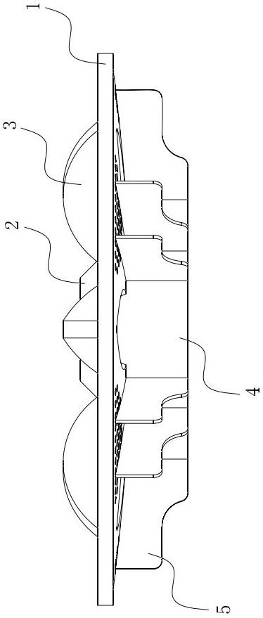
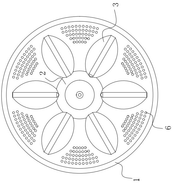
[0037] like Figure 5 , Figure 7 As shown, this embodiment includes a casing 001, an outer cylinder 002, an inner cylinder 003, and a pulsator 008. The outer cylinder 002 is suspended on the Inside the casing 001 , the inner cylinder 003 is rotatably installed on the inner side of the outer cylinder 002 , and the pulsator 008 is rotatably installed on the inner bottom of the inner cylinder 003 . Two rotating shafts (not shown) for driving the rotation of the inner cylinder 003 and the pulsator 008 pass through the outer cylinder 002 from the outside of the bottom of the outer cylinder 002, and are fixedly connected with the inner cylinder 003 and the pulsator 008 respectively. The driving motor 009, the clutch 010, the drain valve 011, and the drain motor (not marked) for controlling the action of the drain valve 011 for providing power for the rotat...


PUM


Abstract

The invention discloses a low-noise anti-winding impeller washing machine. The low-noise anti-winding impeller washing machine comprises a machine shell, an outer barrel, an inner barrel and impellers; a first permanent magnet is arranged at the upper end of the outer side of the outer barrel; a second permanent magnet is arranged on the inner side of the machine shell; and the first permanent magnet and the second permanent magnet are arranged in a magnetic opposite mode. The impellers comprise an upper impeller and a lower impeller; the upper impeller comprises an upper impeller disc, an upper middle boss and upper washing ribs are arranged on the upper surface of the upper impeller disc, and an opening is formed in the top of the upper middle boss. The lower impeller comprises a lower impeller disc, the upper surface of the lower impeller disc is provided with a lower middle boss and lower washing ribs, and the lower washing ribs can make contact with the lower surfaces of the upper washing ribs. A flow channel is defined between the lower middle boss and the lower surface of the upper middle boss. And the lower impeller disc is provided with a flow channel port. Annular reinforcing ribs and impeller blades are arranged on the lower surface of the lower impeller disc, the flow channel opening is formed in the radial outer side of the outermost annular reinforcing rib, and the impeller composed of the impeller blades meets the condition that when the impeller rotates forwards or backwards, water flows upwards or downwards to flow through the flow channel.

Description

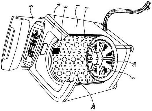
technical field [0001] The invention relates to the field of household appliances, in particular to a low-noise anti-winding pulsator washing machine. Background technique [0002] Washing machines can be divided into three types: stirring type, drum type and pulsator type. [0003] figure 1 A partial sectional view of a conventional pulsator washing machine is shown. see figure 1 , the box body 1 is provided with a cylindrical outer cylinder (not shown) for containing water, and an inner cylinder 2 is rotatably arranged in the outer cylinder, and a plurality of can be arranged on the side wall of the inner cylinder 2 Holes 2a for water to flow between the inner and outer cylinders. A pulsator 3 is provided on the inner bottom of the inner cylinder 2, and the pulsator 3 is connected to a driving shaft (not shown), and the driving shaft is driven by a motor (not shown). The upper surface of the pulsator 3 is provided with a plurality of washing ribs 3a protruding upward ...

Claims


Application Information

Patent Timeline
Patent Type & Authority Applications(China)
IPC IPC(8): D06F23/04D06F17/10D06F37/24
CPCD06F23/04D06F17/10D06F37/24
Inventor 杨汉友
Owner 杨汉友
Learn More