
Camera holder control method, device and equipment and storage medium

A control method and camera technology, which are applied in the field of devices, camera pan-tilt control methods, equipment and storage media, can solve the problems of the motor of the camera pan-tilt being out of step, the monitoring effect cannot be guaranteed, and the errors are accumulated, so as to reduce the recurrence of failures. step probability, improve monitoring effect, improve monitoring effect

Pending Publication Date: 2021-10-08
ZHEJIANG DAHUA TECH CO LTD
View PDF0 Cites 2 Cited by
  • Summary
  • Abstract
  • Description
  • Claims
  • Application Information

AI Technical Summary

Problems solved by technology

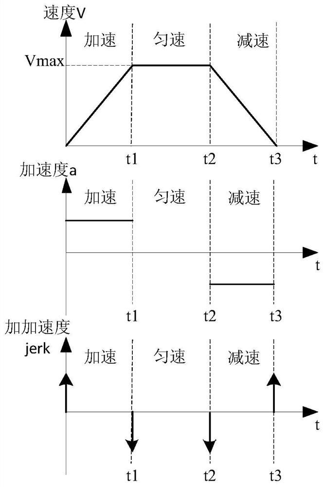
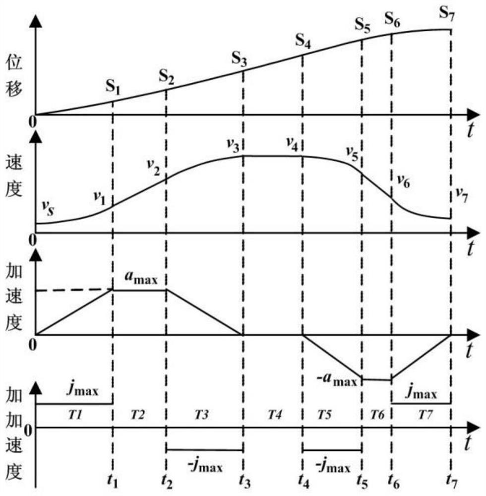
[0003] However, different business scenarios have different requirements for monitoring stability, accuracy, and speed. Traditional camera pan / tilts are generally driven by stepping motors. Through subdivision processing, the motors of camera pan / tilts can be moved by corresponding steps. distance angle, and according to the strategy presented as a single trapezoidal velocity curve or S-shaped acceleration curve to control the motion state of the camera pan / tilt, however, these strategies will make the camera pan / tilt prone to vibrations and relatively slow acceleration / deceleration during motion. slow situation
[0004] Therefore, the existing strategies often cannot guarantee the monitoring effect in different business scenarios
Moreover, due to the difference in the structure and working environment of the camera pan / tilt, selecting the acceleration / deceleration control strategy only according to the business may cause the motor of the camera pan / tilt to lose synchronization, and when this strategy is continued to be used, it may always occur The situation of out of step, which leads to the accumulation of errors

Method used

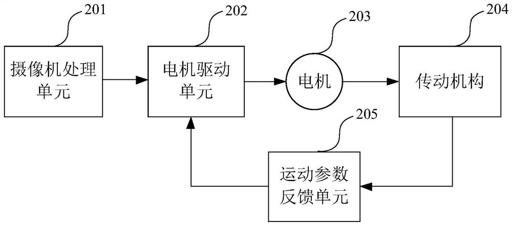

Image

  • Camera holder control method, device and equipment and storage medium
  • Camera holder control method, device and equipment and storage medium
  • Camera holder control method, device and equipment and storage medium

Examples


Embodiment Construction

[0068] In order to make the purpose, technical solutions and advantages of the present application, the following will be described in conjunction with the drawings in the present application embodiment, and is clearly described, and it is understood that the described embodiments are simplified. It is an embodiment of the present application, not all of the embodiments. Based on the embodiments in the present application, all other embodiments obtained by those of ordinary skill in the art without making creative labor premises, all of the present application protected. In the case of an unable conflict, the features and embodiments in the present application can be any combination with each other. Although the logical order is shown in the flowchart, in some cases, the steps shown or described may be performed in the order in which it is in the order here.

[0069] First, some terms in the present application will be explained.

[0070] Obpening: Stepping motors operating by dig...


PUM


Abstract

The invention provides a camera holder control method and device, equipment and a storage medium, relates to the technical field of security and protection, and aims to improve the monitoring effect of a camera. The method comprises the following steps: when a first monitoring target enters a monitoring area of a camera, determining an initial motion strategy adopted by a camera holder for monitoring the monitoring target based on the equipment structure information of the camera holder; controlling the camera holder to rotate based on the initial motion strategy; in the execution process according to the initial motion strategy, determining the motion stage of the camera holder during out-of-step according to the actual rotation angle of the camera holder at each moment and the estimated rotation angle of the camera holder at the corresponding moment determined based on the initial motion strategy; adjusting the initial motion strategy based on the motion stage of the camera holder during out-of-step, and obtaining an adjusted motion strategy; and when the monitoring target of the same type as the first monitoring target is monitored, controlling the camera holder to rotate based on the adjusted motion strategy.

Description

Technical field [0001] This application relates to the field of security technology, providing a camera turbine control method, device, device, and storage medium. Background technique [0002] At present, with the development of artificial intelligence, AI technology, and the user's improvement of camera monitoring requirements, the camera needs to apply to different business scenarios, for example, in the absence of a long distance, The lens of the magnification is fixed-back-round monitoring, or tracks the target of moving at different speeds, or uses a camera to cruise, patrol, and other business scenes. [0003] However, different business scenarios have different requirements for monitoring, accurate, fast and other requirements, and traditional camera turns typically drive the stepping motor, by subdivision, can move the motor moving motor movement At the angle, and according to the strategy presenting a single trapezoidal speed curve or the S-shaped acceleration curve, th...

Claims


Application Information

Patent Timeline
IPC IPC(8): G05D3/20
CPCG05D3/20
Inventor 王明巍杨增启郑伟峰惠森林隋小波
Owner ZHEJIANG DAHUA TECH CO LTD
Learn More