
Heat dissipation system, box body and installation method

A heat dissipation system and cabinet technology, applied in household refrigeration equipment, lighting and heating equipment, defrosting, etc., can solve problems such as short circuit of air inlet and air outlet, limited size and length of condenser, and limited heat dissipation area, etc., to achieve Improve the heat dissipation effect, increase the size, and increase the effect of heat conduction

Inactive Publication Date: 2021-10-08
CHANGHONG MEILING CO LTD
View PDF7 Cites 1 Cited by
  • Summary
  • Abstract
  • Description
  • Claims
  • Application Information

AI Technical Summary

Problems solved by technology

[0004] The object of the present invention is to provide a heat dissipation system, a box body and an installation method. By optimizing the installation angle of the main condenser and the air inlet direction of the air duct system, a partition body is arranged between the air inlet and the air outlet to solve the existing problems. The size and length of the condenser and the heat dissipation area are limited, and the air inlet and outlet are prone to short circuit problems

Method used


Image

  • Heat dissipation system, box body and installation method
  • Heat dissipation system, box body and installation method
  • Heat dissipation system, box body and installation method

Examples


Embodiment 1

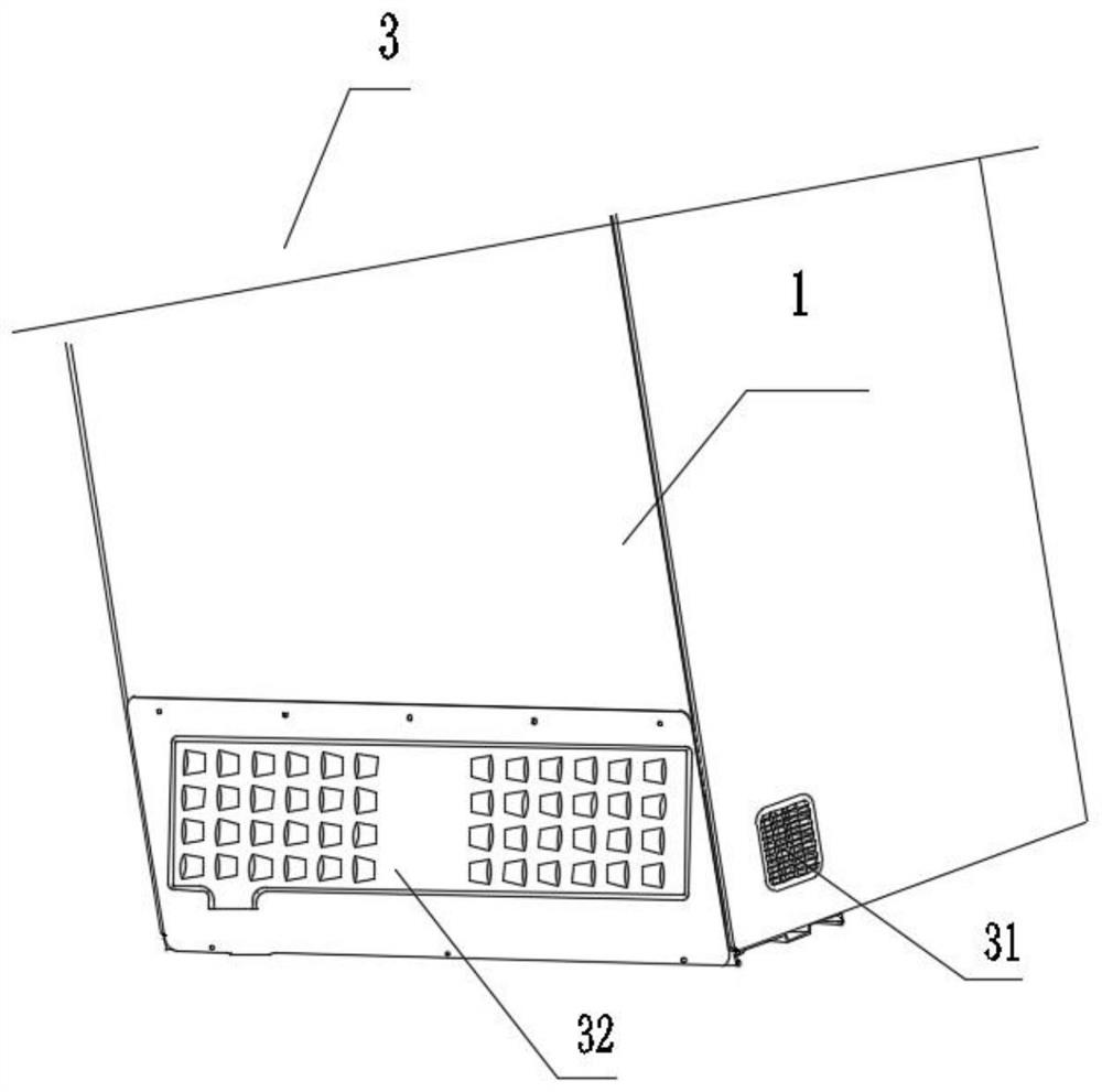
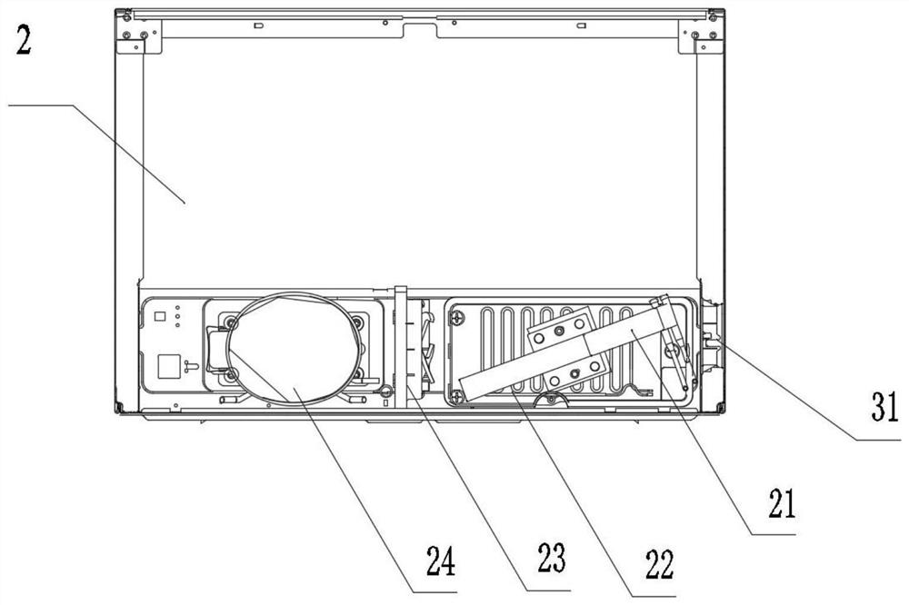
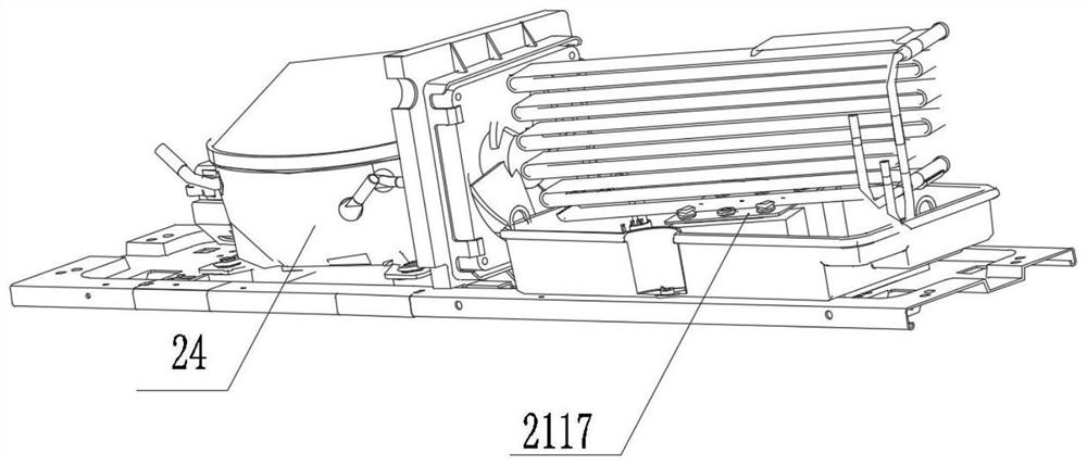
[0049] see Figure 1-2 As shown, the present invention is a heat dissipation system, including an air duct system 3 and a heat dissipation module 2 installed on the bottom plate of the box body 4; the heat dissipation module 2 includes a condenser assembly 21, a water tray 22, a fan assembly 23 and a compressor 24 The condenser assembly 21 includes a main condenser 211 and a sub-condenser 212 connected with the main condenser 211; defrosting water to achieve the purpose of rapid heat dissipation; the water receiving tray 22 is an open box-shaped container, and a mounting platform 221 for installing the main condenser 211 is arranged at the middle position inside the water receiving tray 22; The water tray 22 forms an included angle a in the horizontal direction, and makes the main condenser 211 form an included angle a corresponding to the air inlet direction of the air duct system 3 after assembly. The main condenser 211 and the fan 231 are installed at an included angle, whi...

Embodiment 2

[0055] On the basis of Example 1, as Figure 11-13 As shown, the air channel assembly 31 includes an air channel box 311 and an air channel cover 312; the air channel box 311 includes a channel main body 3111 and a fixing part 3112, and a buckle hole 3110 is opened on the side of the air channel box 311; the channel main body 3111 is The main air inlet channel is provided with a through-hole structure 31111 for ventilation; the fixed part 3112 is arranged around the channel main body 3111 and is provided with an installation hole E31121; the air channel cover 312 includes a ventilation body 3121 and a matching part 3122; Ventilation holes 31211 with a grid structure are provided; the matching part 3122 includes a claw body 31221 and an extension body 31222 that are engaged with the buckle hole 3110 and an extension body 31222. .

[0056] Such as Figure 11-14 As shown, the rear cover 32 includes an air inlet 321 arranged on the right side of the fan assembly 23 and an air ou...

Embodiment 3

[0058] On the basis of the first embodiment, the present application also provides a box, including a box body 1 and a box shell 6; the box body 1 is equipped with the above-mentioned heat dissipation system.


PUM

PropertyMeasurementUnit
Angleaaaaaaaaaa

Abstract

The invention discloses a heat dissipation system, a box body and an installation method, and relates to the technical field of refrigerators. The heat dissipation system comprises an air duct system and a heat dissipation module; the heat dissipation module comprises a condenser assembly, a water pan, a fan assembly and a compressor; the condenser assembly comprises a main condenser and an auxiliary condenser connected with the main condenser; the auxiliary condenser is mounted in a horizontal area at the bottom in the water pan; a mounting table for mounting the main condenser is arranged in the middle of the interior of the water pan; an included angle a is formed between the mounting table and the water pan in the horizontal direction, and a correspondingly identical included angle a is formed between the assembled main condenser and the air inlet direction of the air duct system; and the air duct system comprises an air duct assembly and a rear cover which are arranged on the box body. According to the heat dissipation system, the installation angle of the main condenser is optimized, a partition body is arranged between an air inlet and an air outlet, and the problems that an existing condenser is limited in size and heat dissipation area, and air path short circuit is likely to be formed are solved.

Description

technical field [0001] The invention belongs to the technical field of refrigerators, and in particular relates to a cooling system, a box body and an installation method. Background technique [0002] In order to reduce the overall size and increase the heat dissipation capacity of existing household refrigerators, the heat dissipation system is generally arranged in the compressor compartment of the refrigerator, and the heat dissipation is realized by forced air circulation. In the industry, the condenser and the compressor are generally arranged on both sides respectively, and the heat exchange is realized by forced convection through a fan in the middle. In this way, generally the air inlet is set on one side of the rear cover of the press chamber, and the air outlet is arranged on the other side of the rear cover of the press chamber. [0003] Chinese invention patent CN110375506A discloses a refrigerator that dissipates heat from the bottom. The air enters the compre...

Claims


Application Information

Patent Timeline
IPC IPC(8): F25D23/00F25D21/14
CPCF25D23/003F25D23/006F25D21/14F25D2321/144
Inventor 程春明刘全义王瑶
Owner CHANGHONG MEILING CO LTD
Learn More