Data reading and writing method
A technology of data reading and writing and reading and writing equipment, which is applied in electromagnetic radiation induction, electrical recording, printing, etc., and can solve problems such as complex operation
- Summary
- Abstract
- Description
- Claims
- Application Information
AI Technical Summary
Problems solved by technology
Method used
Image
Examples
Embodiment 1
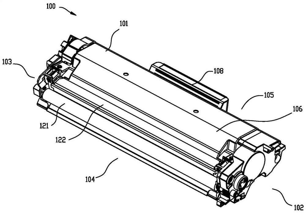
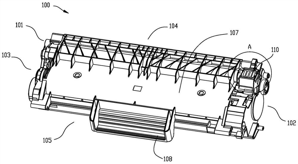
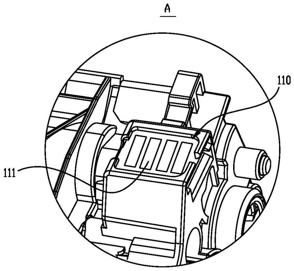
[0091] The present embodiment provides a package that can be used for packaging a consumable box (such as a developer cartridge 100). The developer cartridge 100 is detachably installed in the main body of a laser printer. chip 110, such as Figure 1 to Figure 3 As shown, in the length direction of the developing cartridge 100, the developing cartridge 100 has a left end 103 and a right end 102; in the width direction of the developing cartridge 100, the developing cartridge 100 has a front end 104 and a rear end 105; in the height direction of the developing cartridge 100 , the developing cartridge 100 has an upper surface 106 and a lower surface 107 . Front end 104 places of developing cartridge 100 are provided with parts such as developing roller 121, powder outlet knife 122; The position of the consumables chip 110 disposed on the box body 101 is not limited. In this embodiment, the consumables chip 110 is disposed on the lower surface 107 of the case body 101, and is cl...
Embodiment 2
[0097] According to this embodiment, the package can also be a package assembly, including a first package and a second package, the first package is used to accommodate the consumable box, and the second package can be sleeved outside the first package. Among them, the first package can be a cotton tray, a paper tray, a bubble bag, a packaging bag, etc., which are located inside the package as a whole, and the second package can be the packaging box structure described in the first embodiment. The outermost layer in the whole.
[0098] Such as Image 6 with Figure 7 As shown, the package 30 according to this embodiment includes a first package 40 and a second package 50. The second package 50 is the same package structure as the package 10 in Embodiment 1. In its width direction Have top surface 51, bottom surface 52, and front 53 and rear surface 54, have left side 55 and right side 56 on its length direction, second package 50 has accommodating part 57, and the open end ...
Embodiment 3
[0100] On the basis of the above-mentioned embodiments, this embodiment further provides another package structure. A peelable part can be further provided on the package provided with an operable part, and the peelable part at least covers the operable part. Used to limit the exposure of operable parts to the outside of the package. Such as Figure 10 As shown, the package 60 has the same operable portion 20 as in the first and second embodiments, and a peelable portion 24 is provided on the outer surface or inner surface of the operable portion 20 in a peelable manner. The covering size of the peelable portion 24 is larger than The peripheral size of the operable part 20 can be made of a material such as a transparent film or a label, which is covered on the operable part 20 by pasting, welding, etc., so as to seal and protect the package 60 . After the peelable portion 24 is peeled off from the package 60, the operable portion 20 can be exposed. Prompt slogans can also be...
PUM
 Abstract
Description
Claims
Application Information
 - R&D
- Intellectual Property
- Life Sciences
- Materials
- Tech Scout
- Unparalleled Data Quality
- Higher Quality Content
- 60% Fewer Hallucinations
Browse by: Latest US Patents, China's latest patents, Technical Efficacy Thesaurus, Application Domain, Technology Topic, Popular Technical Reports.
© 2025 PatSnap. All rights reserved.Legal|Privacy policy|Modern Slavery Act Transparency Statement|Sitemap|About US| Contact US: help@patsnap.com


