
Phosphating device for manufacturing metal wire rope

A technology of metal wire rope and wire rope, which is applied in the field of wire rope, can solve the problems of inability to carry out further processing, reduce work efficiency, time-consuming and labor-intensive, etc., and achieve the effect of speeding up the conjunctiva, saving time, and improving processing efficiency

Inactive Publication Date: 2021-10-01
徐州国研新材料科技有限公司
View PDF0 Cites 0 Cited by
  • Summary
  • Abstract
  • Description
  • Claims
  • Application Information

AI Technical Summary

Problems solved by technology

[0003] In the process of metal wire rope processing, it needs to be phosphating. The purpose of phosphating is mainly to provide protection for the base metal and prevent the metal from being corroded to a certain extent; it is used as a primer before painting to improve the adhesion of the paint film layer and anti-corrosion ability; it is used for anti-friction lubrication in the metal cold working process. The phosphating step needs to immerse the silk rope in the phosphating solution and rely on chemical reactions to achieve phosphating. It is widely used. The existing phosphating device needs Manually putting the silk rope into the phosphating tank is time-consuming and laborious, and the blank period in the phosphating process cannot be further processed, wasting a lot of time and reducing work efficiency

Method used

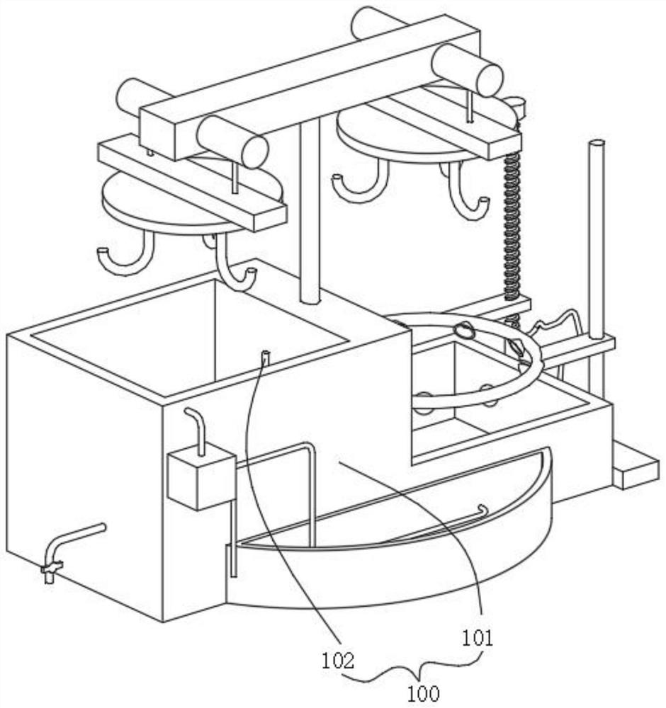
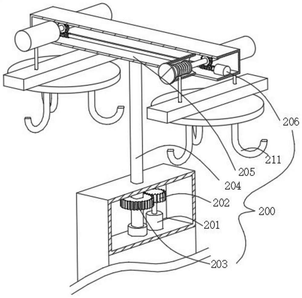
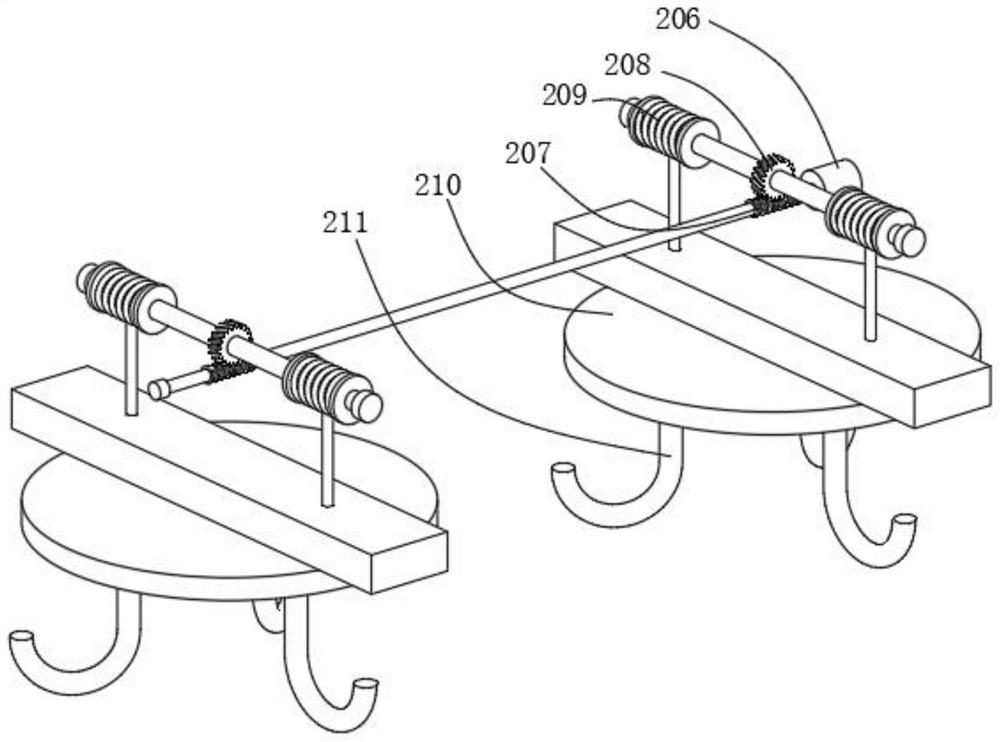

Image

  • Phosphating device for manufacturing metal wire rope
  • Phosphating device for manufacturing metal wire rope
  • Phosphating device for manufacturing metal wire rope

Examples


Embodiment 1

[0049] combine figure 1 , 2 As shown in and 3, the phosphating device for making wire rope provided by the present invention includes a body 100, a liquid immersion mechanism 200, an air-drying mechanism 300, a collection mechanism 400 and a return mechanism 500, and the body 100 includes a phosphating tank 101 and is fixed in The heating tubes 102 on both sides of the phosphating tank 101, the phosphating tank 101 has a built-in cavity, and the immersion mechanism 200 includes a first motor 201 fixed in the cavity, a drive gear 202 fixed to the output end of the first motor 201, The transmission shaft 204 that is rotatably installed in the cavity, the transmission gear 203 that is sleeved on the transmission shaft 204 and meshes with the drive gear 202 for transmission, the housing 205 that is fixed on the top of the transmission shaft 204, and the second housing that is fixed in the housing 205 Second motor 206, the connecting shaft fixedly connected to the output end of th...

Embodiment 2

[0054] combine Figure 4 and 5 As shown, on the basis of Embodiment 1, the air-drying mechanism 300 includes a third motor 301 fixed on one side of the phosphating tank 101, a screw rod 302 fixed on the output end of the third motor 301, a screw rod 302 fixed on the phosphating tank 101- The slide bar on the side, the connecting plate 303 suitable for sliding relative to the screw rod 302 and the sliding bar, the guide ring 304 fixed on the two connecting plates 303, the guide cover fixed on the inside of the guide ring 304 and fixed on the The fan 305 on one side of the phosphating tank 101, the output pipe on the fan 305 is connected to the guide ring 304, the third motor 301 starts to drive the screw 302 to rotate, so that the connecting plate 303 rises or falls, and the guide ring 304 follows the connecting plate 303 Moving, the fan 305 transports the external wind to the guide ring 304 through the pipeline, and then through the guide cover to air-dry the silk rope after ...

Embodiment 3

[0057] combine Figure 4 , 6 , 7, 8 and 9, in the above embodiment, the collection mechanism 400 includes a filter plate 401 fixed on the inner side walls of the phosphating tank 101, a collection box placed in the middle of the bottom wall of the phosphating tank 101 402, a plurality of filter holes opened at the bottom of the collection box 402, and handles fixed on both sides of the collection box 402, the filter plates 401 on both sides are inclined, and the two filter plates 401 are respectively located on both sides of the collection box 402 After the used phosphating solution is discharged, the filter plate 401 filters the impurities in the liquid, and the impurities on the filter plate 401 slide into the collection box 402 to collect the impurities without manual cleaning, saving time and effort.

[0058] Specifically, the collecting mechanism 400 also includes a fourth motor 403 fixed on the phosphating tank 101, a first drive shaft fixed on the output end of the fou...


PUM


Abstract

The invention discloses a phosphating device for manufacturing a metal wire rope. The device comprises a machine body, an immersion mechanism, an air drying mechanism, a material collecting mechanism and a backflow mechanism, the machine body comprises a phosphating pool and heating pipes fixedly installed on the two sides in the phosphating pool, a cavity is formed in the phosphating pool, the immersion mechanism comprises a first motor fixedly mounted in the cavity, a driving gear fixedly connected to the output end of the first motor, a transmission shaft rotatably mounted in the cavity, a transmission gear which sleeves the transmission shaft and is in meshing transmission with the driving gear, a shell fixedly connected to the top end of the transmission shaft, a second motor fixedly mounted in the shell, a hanging scaffold fixedly connected to the end of a connecting rope, and a plurality of clamping hooks fixedly connected to the bottom of the hanging scaffold, the air drying mechanism is located on one side of the phosphating pool and used for air-drying phosphating liquid on the wire rope, the material collecting mechanism is located on the phosphating pool and used for receiving impurities generated in the phosphating reaction of the wire rope, and the backflow mechanism is located on the outer side of the phosphating pool and used for receiving the phosphating solution dripping when the position of the wire rope is changed.

Description

technical field [0001] The invention relates to the technical field of wire ropes, in particular to a phosphating device for making metal wire ropes. Background technique [0002] Silk rope, Chinese vocabulary, silk rope or fishing line, metal wire rope is a tool that is frequently used in daily life. Because the overall toughness of metal wire rope is relatively good, it is often used for consignment or hanging The user can also select the thickness specification of the wire rope according to the situation; the existing wire rope has certain disadvantages in use, because the shape of the wire rope is mostly cylindrical. [0003] In the process of metal wire rope processing, it needs to be phosphating. The purpose of phosphating is mainly to provide protection for the base metal and prevent the metal from being corroded to a certain extent; it is used as a primer before painting to improve the adhesion of the paint film layer and anti-corrosion ability; it is used for anti-...

Claims


Application Information

Patent Timeline
Patent Type & Authority Applications(China)
IPC IPC(8): C23C22/73C23C22/82C23C22/86B01D29/01B01D29/72B01D29/94B01D29/52
CPCC23C22/73C23C22/82C23C22/86B01D29/01B01D29/72B01D29/94B01D29/52
Inventor 梁超
Owner 徐州国研新材料科技有限公司
Learn More