
A multi-directional adjustable composite ultrasonic-assisted EDM spindle

A composite ultrasonic and electric spark technology, applied in the direction of electric processing equipment, metal processing equipment, manufacturing tools, etc., can solve the problems of no spindle device, etc., and achieve the effect of low price, stable performance, and high electromechanical conversion rate

Active Publication Date: 2022-08-02
DALIAN UNIV
View PDF0 Cites 0 Cited by
  • Summary
  • Abstract
  • Description
  • Claims
  • Application Information

AI Technical Summary

Problems solved by technology

At present, the existing ultrasonic-assisted EDM spindle can basically only complete a single form or a combination of longitudinal and torsional ultrasonic vibrations, and there are few cases where horizontal ultrasonic vibration is added to the EDM spindle, and there is no one that can superimpose multiple vibrations in EDM. A Spindle Device with Ultrasonic Vibration

Method used


Image

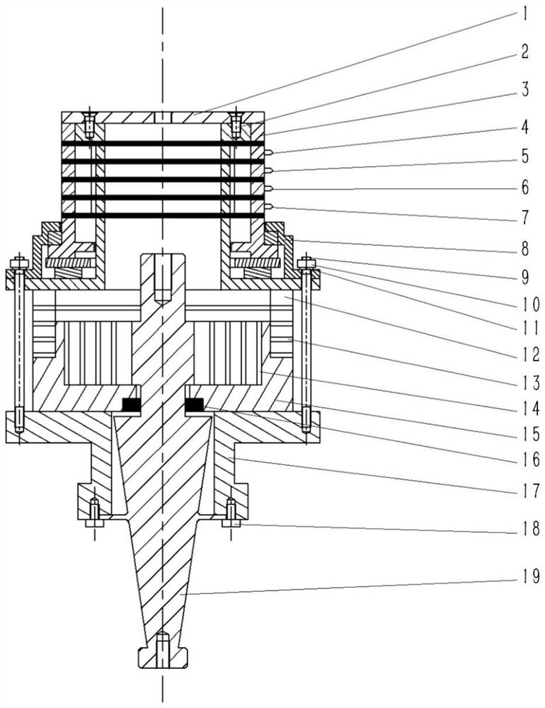
  • A multi-directional adjustable composite ultrasonic-assisted EDM spindle
  • A multi-directional adjustable composite ultrasonic-assisted EDM spindle
  • A multi-directional adjustable composite ultrasonic-assisted EDM spindle

Examples


Embodiment 1

[0028] like Figure 1-3 As shown, this embodiment provides a multi-directional adjustable composite ultrasonic-assisted EDM spindle, including a top cover 1 , an electric slip ring 3 , a thrust sliding bearing 8 , an ultrasonic transducer 12 , a sleeve 17 , and a horn 19 . The top cover 1 is provided with a spiral through hole in the middle, which is used to connect the rotating spindle of the EDM machine; the bottom end face of the top cover 1 is connected with the electric slip ring 3 to transmit the rotating motion of the spindle, and is fixed with a flat-head screw 2; the thrust sliding bearing 8 is sleeved on the bottom of the electric slip ring 3 to bear axial thrust and limit axial movement, wherein the housing of the thrust sliding bearing 8 is in clearance fit with the stator of the electric slip ring 3 . The bottom of the ultrasonic transducer 12 is a limit chuck 15, a circular piezoelectric stack 13 that generates longitudinal vibration is fixed on a card table on t...

Embodiment 2

[0030] This embodiment provides a method for using a multi-directional adjustable composite ultrasonic-assisted spark spindle, which includes longitudinal ultrasonic vibration, longitudinal-torsional composite ultrasonic vibration, horizontal ultrasonic vibration and three-dimensional elliptical ultrasonic vibration.

[0031] 1. Longitudinal ultrasonic vibration: The positive pole of the ultrasonic power supply is connected to pin B, and the negative pole of the ultrasonic power supply is connected to pin A. By adjusting the ultrasonic parameters, the longitudinal ultrasonic vibration is assisted EDM.

[0032] 2. Longitudinal-torsional composite ultrasonic vibration: the positive pole of the ultrasonic power supply is connected to pin B, and the negative pole of the ultrasonic power supply is connected to pin A. By adjusting the ultrasonic parameters, the spindle rotates during processing to realize vertical-torsional composite ultrasonic vibration-assisted EDM.

[0033] 3. Hor...


PUM


Abstract

The invention discloses a multi-directional adjustable composite ultrasonic auxiliary electric spark spindle, comprising: a top cover, an electric slip ring, a thrust sliding bearing, an ultrasonic transducer, a sleeve and a horn; a rotor part of the electric slip ring It is connected with the top cover to transmit the rotational motion of the main shaft; the thrust sliding bearing is sleeved on the bottom of the electric slip ring, and cooperates with the stator of the electric slip ring to bear the axial thrust and limit the axial movement; the ultrasonic replacement The energy device is located between the bearing seat of the thrust sliding bearing and the front end surface of the sleeve, and is used to convert the ultrasonic oscillation signal output by the ultrasonic generator into mechanical energy; the front end of the horn is located in the electric slip ring cavity, and the rear end is located in the electric slip ring cavity. Pass through the ultrasonic transducer and the sleeve in sequence. The invention combines longitudinal ultrasonic vibration, horizontal ultrasonic vibration and longitudinal-torsional composite ultrasonic vibration into one, and can realize the compounding and transformation of various ultrasonic vibrations during processing, and further improve the efficiency and precision of electrical discharge machining.

Description

technical field [0001] The invention relates to the technical field of ultrasonic electric spark compound machining, in particular to a multi-directional adjustable compound ultrasonic auxiliary electric spark spindle that combines longitudinal, horizontal and longitudinal torsional compound ultrasonic vibrations. Background technique [0002] With the development of aviation and aerospace manufacturing technology, the manufacturing demand for various three-dimensional complex structures, micro-sized pores and shafts is increasing day by day, and at the same time, higher requirements are placed on the manufacturing accuracy of parts. As a non-contact machining method, EDM has been widely used in the machining of difficult-to-cut materials and the manufacture of precision and complex parts. The pumping effect can effectively speed up the cooling and circulation of the working fluid, accelerate the deionization of the inter-electrode medium, significantly improve the processin...

Claims


Application Information

Patent Timeline
Patent Type & Authority Patents(China)
IPC IPC(8): B23H1/00B23H11/00
CPCB23H1/00B23H11/00
Inventor 王元刚唐欣王慧王珍刘安生甄恒洲郑双阳李淑娴
Owner DALIAN UNIV
Learn More