Automatic valve with pressure relief protection structure and implementation method of automatic valve

A protective structure and automatic valve technology, which is applied in the direction of sliding valve, valve shell structure, valve details, etc., can solve the problems of manpower consumption, waste of resources, troublesome operation, etc.

Active Publication Date: 2021-09-28
JIANGSU JINSHENGYUAN SPECIAL VALVE
View PDF6 Cites 0 Cited by
  • Summary
  • Abstract
  • Description
  • Claims
  • Application Information

AI Technical Summary

Problems solved by technology

[0005] The purpose of the present invention is to provide an automatic valve with a pressure relief protection structure and its implementation method. This device is used to work, thereby solving the problem that when the water stop valve is opened in the above background, it is usually necessary to use external force to open the valve to realize water discharge. , not only is it troublesome to operate and consumes manpower, but also does not make good use of the water pressure, resulting in a waste of resources

Method used


Image

  • Automatic valve with pressure relief protection structure and implementation method of automatic valve
  • Automatic valve with pressure relief protection structure and implementation method of automatic valve
  • Automatic valve with pressure relief protection structure and implementation method of automatic valve

Examples


Embodiment approach , 1 Embodiment approach

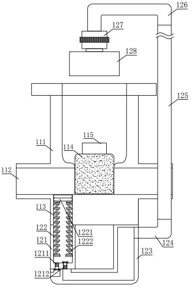
[0042] In order to further and better explain the above-mentioned embodiments, the present invention also provides an embodiment, a method for implementing an automatic valve with a pressure relief protection structure, comprising the following steps:

[0043] Step 1: When the water pressure in the pressure collecting chassis 1 increases, the pressure will push down the rubber pad 1221, and the air in the communication hole 113 will enter the L-shaped connecting cylinder 123 through the second one-way valve 1212, In the first hard connection pipe 124, the telescopic connection long pipe 125 and the second hard connection pipe 126;

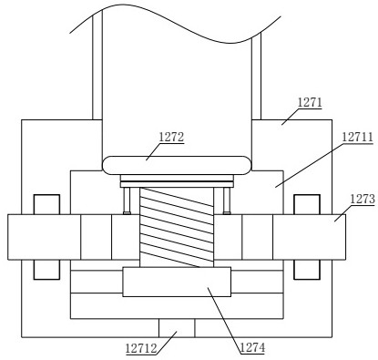
[0044] Step 2: By turning the switch wheel 1273, driven by the second threaded column 12737, the T-shaped installation round block 12735 drives the air outlet rubber pad 1272 to move downward, the L-shaped connecting cylinder 123, the first hard connecting pipe 124, The air in the telescopic connection long pipe 125 and the second hard connection p...


PUM


Abstract

The invention discloses an automatic valve with a pressure relief protection structure and an implementation method of the automatic valve. The automatic valve comprises a pressure collection base plate, an installing plate and a gate opening device, when the valve needs to be opened, a T-shaped installing round block drives an air outlet rubber pad to move downwards under driving of a second threaded column by screwing an opening and closing rotating wheel, air stored in an L-shaped connecting cylinder, a first hard connecting pipe, a telescopic connecting long pipe and a second hard connecting pipe can enter a pushing inner groove, the compressed air pushes an air pressure pushing block, and when an operator rotates a circular rotating wheel, under pushing of a one-way circular rotating plate, an operator can rotate the circular rotating wheel in a more labor-saving mode. The invention further discloses an implementation method of the automatic valve with the pressure relief protection structure, when the water pressure in a pressure collection base plate is increased, the pressure can downwards press a pressing rubber pad, and the air in a communicating hole can enter the L-shaped connecting cylinder, the first hard connecting pipe, the telescopic connecting long pipe and the second hard connecting pipe through a second one-way valve.

Description

technical field [0001] The invention relates to the technical field of valves, in particular to an automatic valve with a pressure relief protection structure and an implementation method thereof. Background technique [0002] A valve is a mechanical device that controls the flow, flow direction, pressure, temperature, etc. of a flowing fluid medium, and a valve is a basic component in a piping system. Valve fittings are technically the same as pumps and are often discussed as a separate category. The valve can be operated manually or by handwheel, handle or pedal, and can also be controlled to change the pressure, temperature and flow of the fluid medium. Valves can operate continuously or repeatedly in response to these changes, such as safety valves installed in hot water systems or steam boilers. Valves are automatically controlled in more complex control systems as required by an external input (ie, adjusting the changing set point of the flow through the pipeline). ...

Claims


Application Information

Patent Timeline
Patent Type & Authority Applications(China)
IPC IPC(8): F16K3/24F16K3/30F16K3/314F16K27/04F16K31/50F16K31/60F16K47/00F16L55/02F16L55/07
CPCF16K3/24F16K3/30F16K3/314F16K27/041F16K31/50F16K31/60F16K47/00F16L55/02F16L55/07
Inventor 毛春龙毛金根陈善俊
Owner JIANGSU JINSHENGYUAN SPECIAL VALVE
Why Eureka
Try Eureka