
Hemostatic clamp

A technology of hemostatic clips and clips, applied in the field of hemostatic clips, can solve problems such as patient discomfort, achieve the effects of wide application, convenient operation, and avoid medical safety accidents

Pending Publication Date: 2021-09-28
江苏欣普瑞医疗科技有限公司
View PDF0 Cites 1 Cited by
  • Summary
  • Abstract
  • Description
  • Claims
  • Application Information

AI Technical Summary

Problems solved by technology

When clamping the hemostat, in order to lock the hemostatic clip, it is necessary to move the handle of the hemostatic clip inward for a short distance, so that the lock hooks at the handle of the hemostatic clip intersect with each other, and then loosen to realize the mutual hooking of the lock hooks. During this process, the head of the hemostatic clip will have an excessive clamping force on the tissue that needs to be hemostatic, which will easily cause discomfort to the patient

Method used


Image

  • Hemostatic clamp
  • Hemostatic clamp
  • Hemostatic clamp

Examples


specific Embodiment approach 1

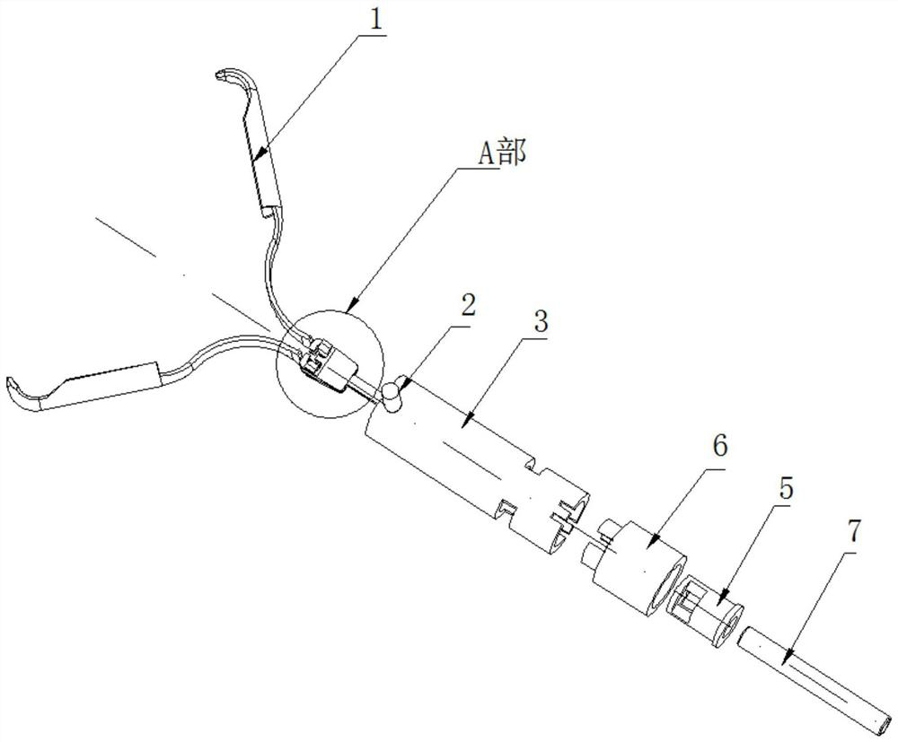
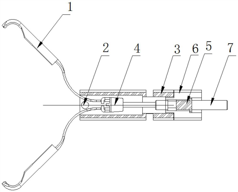
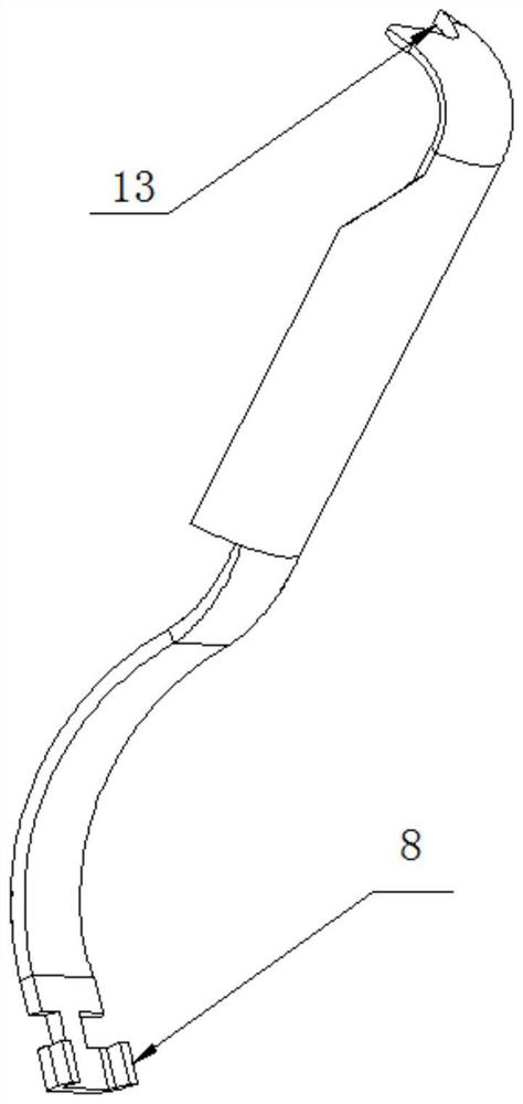
[0027] like Figure 1-Figure 7 As shown, the specific implementation mode adopts the following technical scheme: it includes:

[0028] Clip 1, the number of clips 1 is two, arranged symmetrically up and down, and the tail end of each clip 1 is integrally formed with a tail hook 8;

[0029] Pull rod 4, the number of said pull rod 4 is one, and its head end is integrally formed with upper and lower two buckle positions 10, and the above-mentioned tail hook 8 is stuck in the buckle position 10;

[0030] Bracket 3, the outer ring wall of the bracket 3 is provided with two upper and lower opening grooves 9, the above-mentioned tail hook 8 is movably clamped in the opening groove 9, and the tail end of the bracket 3 is integrally formed with two front and rear bending pieces 12 , the outer wall of the arc-shaped part at the tail of the above-mentioned clip 1 interferes with and is arranged on the inner ring wall of the first port of the bracket 3;

[0031] A shaft sleeve 6, the he...

specific Embodiment approach 2

[0041] see Figure 8 The difference between this specific embodiment and the first specific embodiment is that: the mandrel 5 is arranged in a stepped drum-shaped structure, the above-mentioned bending piece 12 is interlocked with the steps in the stepped drum-shaped mandrel 5 , and the rest The structure and connection method are the same as those in the first embodiment.


PUM


Abstract

The invention relates to the technical field of medical equipment, and in particular relates to a hemostatic clamp. A tail hook is integrally formed at the tail end of each clamp piece; an upper buckle position and a lower buckle position are integrally formed at the head end of a pull rod, and the tail hook is clamped in the buckle positions; an upper opening groove and a lower opening groove are arranged in the outer ring wall of a support, the tail hook is movably clamped in the opening grooves, a front bending piece and a rear bending piece are integrally formed at the tail end of the support, and the outer wall of the arc-shaped portion of the tail of the clamping piece abuts against the inner ring wall of the head port of the support; the head end of a shaft sleeve is inserted into the tail end of the support, and a boss at the head end of the shaft sleeve is adjacent to the tail end of the support; the mandrel is inserted into the shaft sleeve, and a front clamping groove and a rear clamping groove are formed in the head end of the mandrel; the bending sheet penetrates through the notches in the front and rear side walls of the head end of the shaft sleeve and then is clamped with the clamping groove; and the head end of a butt joint pipe penetrates through the mandrel and then is fixed to the tail end of the pull rod. During hemostasis locking, the phenomenon of excessive clamping is avoided, discomfort to a patient is avoided, the operation is convenient, and the hemostasis clamp can be widely applied.

Description

technical field [0001] The invention relates to the technical field of medical equipment, in particular to a hemostatic clip. Background technique [0002] Hemostatic clips are one of the medical devices used for hemostasis in surgery. Generally, a clip similar to a scissors structure is used. When clamping the hemostat, in order to lock the hemostatic clip, it is necessary to move the handle of the hemostatic clip inward for a short distance, so that the lock hooks at the handle of the hemostatic clip intersect with each other, and then loosen to realize the mutual hooking of the lock hooks. During this process, the head of the hemostatic clip will have an excessive clamping force on the tissue that needs to be hemostatic, which will easily cause discomfort to the patient. Contents of the invention [0003] The purpose of the present invention is to provide a hemostatic clip aimed at the defects and deficiencies of the prior art, which adopts a split structure, and when...

Claims


Application Information

Patent Timeline
IPC IPC(8): A61B17/122A61B17/128
CPCA61B17/1227A61B17/1285A61B2017/12004
Inventor 李兆飞
Owner 江苏欣普瑞医疗科技有限公司
Learn More